

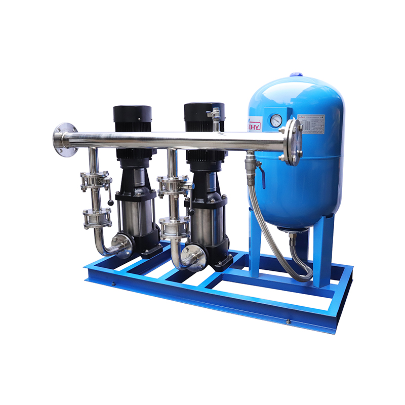
Full Automatic Constant Pressure Variable Frequency Water Supply Equipment is a new generation of hi...
See Details
Single-stage Single-suction Centrifugal Pump Uses Simple Hydraulics
Industry News-A Simple Structure With a Clear Flow Path
Industrial pumping does not always require a complicated hydraulic arrangement. In many water and process systems, a straightforward centrifugal structure can provide a practical way to move liquid from one point to another. This is where the Single-stage Single-suction Centrifugal Pump has an important place in industrial equipment.
Its name already explains two key structural features. “Single-stage” means the pump uses one impeller stage to generate hydraulic energy. “Single-suction” means liquid enters the impeller from one side. These characteristics create a relatively direct internal flow path, making the pump easier to classify according to its hydraulic structure.
For equipment distributors and engineering suppliers, understanding this structure helps when matching pump models to different system requirements.
What Happens Inside the Pump?
The working process starts at the suction inlet. Liquid enters the pump casing and reaches the impeller eye. Once the impeller rotates, centrifugal force moves the liquid outward toward the impeller perimeter.
The casing then guides the moving liquid toward the discharge outlet. During this process, part of the mechanical energy supplied by the motor is converted into pressure energy.
The Single-stage Single-suction Centrifugal Pump therefore relies on a relatively compact sequence: suction, impeller rotation, radial movement, casing flow, and discharge. Each section has a specific role, and the relationship between these components determines the hydraulic behavior of the complete unit.
Impeller Design Shapes Hydraulic Behavior
The impeller is at the center of the pumping process. Its diameter, blade geometry, passage shape, and rotational speed influence how liquid moves inside the pump.
Different impeller configurations can be developed for different flow and head requirements. A pump designed for relatively large flow may use a hydraulic geometry different from one intended for greater pressure generation.
This is one reason the Single-stage Single-suction Centrifugal Pump should not be identified only by its external appearance. Two pumps can share a similar casing shape yet have different hydraulic characteristics because of their impeller dimensions and internal passages.
For manufacturers, controlling these relationships is an important part of pump design and production.
Casing Turns Motion Into Useful Pressure
The casing is more than an enclosure around the rotating assembly. Its internal passage helps collect liquid leaving the impeller and direct it toward the discharge side.
Depending on the pump structure, the casing may use a volute-shaped passage that gradually manages liquid velocity as flow moves toward the outlet. The geometry of this passage has a direct relationship with hydraulic performance.
In a Single-stage Single-suction Centrifugal Pump, casing and impeller design need to work as a matched hydraulic pair. Changing one component can influence the flow pattern inside the other, which is why dimensional coordination matters during manufacturing.
Shaft Alignment Connects the Mechanical Assembly
The pump shaft transfers rotational power from the drive unit to the impeller. Its position needs to remain properly related to the casing, impeller, bearing arrangement, and sealing section.
For industrial equipment suppliers, shaft configuration is an important product detail because it affects how the pump connects to the wider drive system.
The mechanical arrangement also influences how manufacturers organize machining and assembly processes. Shaft dimensions, impeller mounting, bearing positions, and coupling arrangements all need to correspond to the selected pump configuration.
This gives the Single-stage Single-suction Centrifugal Pump a useful combination of hydraulic and mechanical characteristics within one equipment package.
Flow Rate and Head Guide Model Selection
Pump selection begins with the liquid movement required by the system. Flow rate describes how much liquid needs to pass through the pump during a given period, while head represents the energy required to move that liquid through the system.
These two parameters provide a starting point for choosing a suitable pump model. Pipe diameter, system resistance, liquid characteristics, inlet conditions, and operating speed can also influence the final selection.
For distributors and project suppliers, presenting these details clearly makes the Single-stage Single-suction Centrifugal Pump easier to match with industrial applications.
Related products
-
-
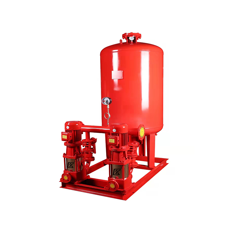
The Automatic Frequency Conversion Constant Pressure Fire Water Supply Equipment is designed and dev...
See Details -
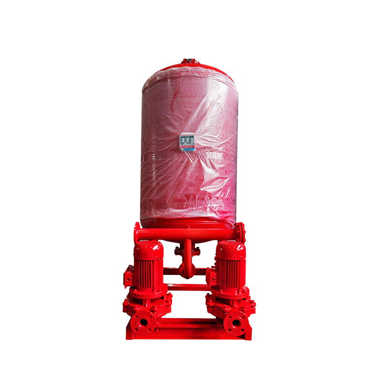
The Fire Fighting Air Pressure Water Supply Equipment typically consists of a pressure tank, pump un...
See Details -
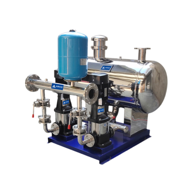
Non-negative pressure water supply equipment is a system composed of a non-negative pressure tank, p...
See Details -
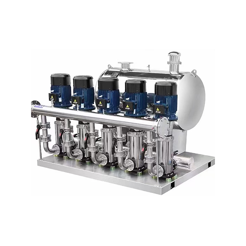
Traditional water supply methods rely heavily on water tanks, which are typically filled with water ...
See Details -
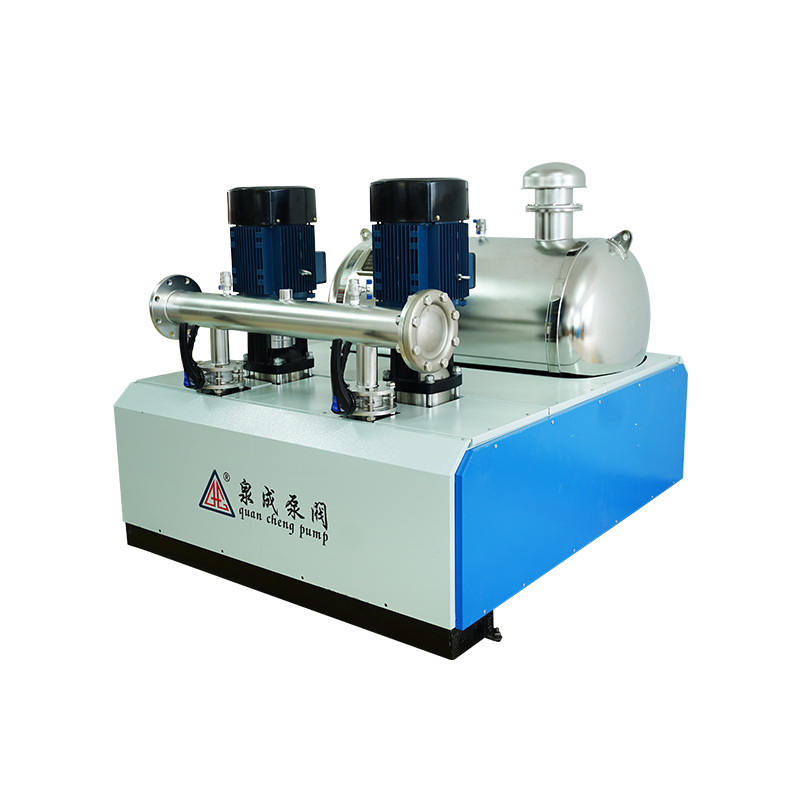
Product OverviewThe Non-negative Pressure Booster Steady Flow Water Supply Equipment uses the munici...
See Details -
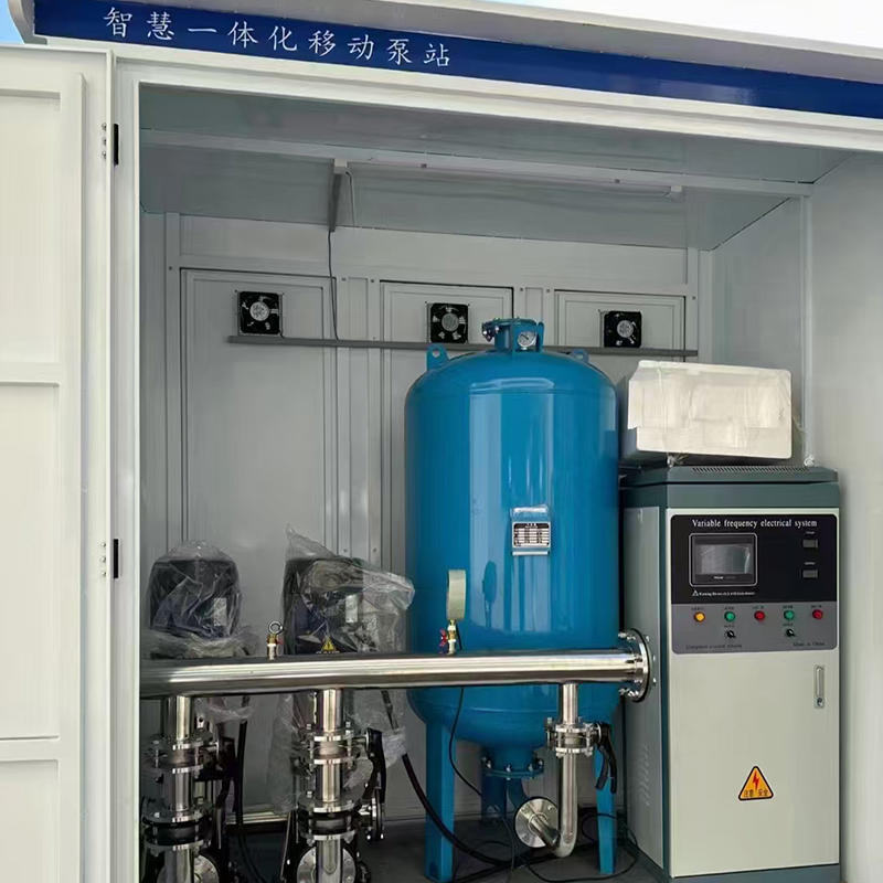
The Intelligent Constant Pressure Variable Frequency Water Supply Equipment is a water supply system...
See Details -
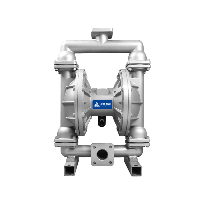
The QBY Air Operated Double Diaphragm Pump produced by our company is a new type of transport machin...
See Details
Copyright © Zhejiang Chuangken Fluid Co., Ltd. All Rights Reserved.
Intelligent Constant Pressure Water Supply System Factory
 浙公网安备33032402001888号
