

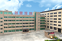
Continuously absorb and introduce excellent technologies based on actual conditions.

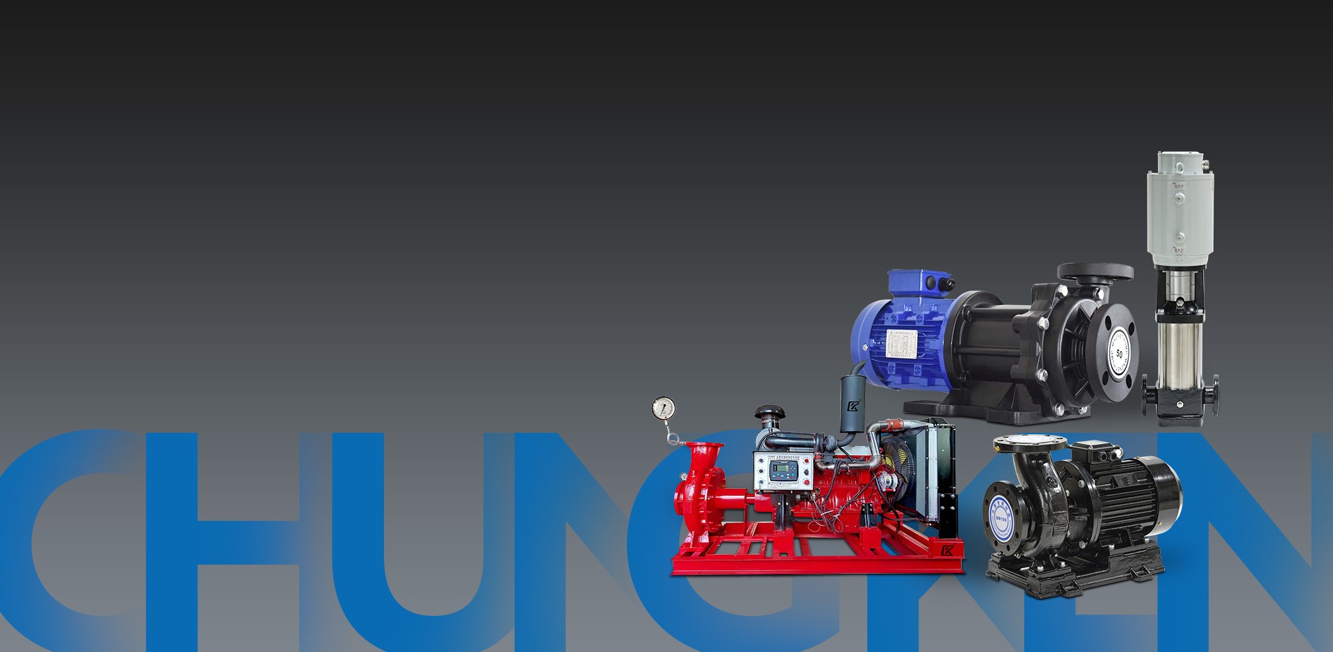 Water Pump
Production ExpertsLeading the green revolution of high-quality water pumps.
Our Products For Your Business
VIEW MORE >>
- Water Supply Equipments
- Diaphragm Pumps
- Magnetic Drive Pumps
- Pipeline Pumps
- Centrifugal Pumps
- Self-Priming Pumps
- Screw Pumps
- Fire Pumps
- Sewage Pumps
- Diesel Engine Pump Sets
- Electrical Control Cabinets
- Irrigation Pumps
- Aquaculture Water Pumps
- Booster Pumps
- Submersible Pumps
- Vacuum Pumps
- Industrial Pumps
- Pump Accessories
-
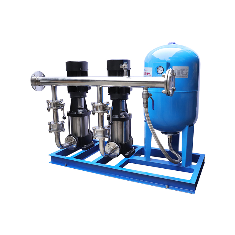 Full Automatic Constant Pressure Variable Frequency Water Supply Equipment
Full Automatic Constant Pressure Variable Frequency Water Supply Equipment is a new generation of hi...
-
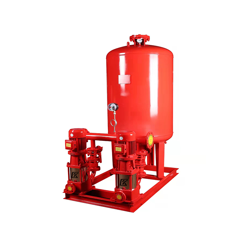 Automatic Frequency Conversion Constant Pressure Fire Water Supply Equipment
The Automatic Frequency Conversion Constant Pressure Fire Water Supply Equipment is designed and dev...
-
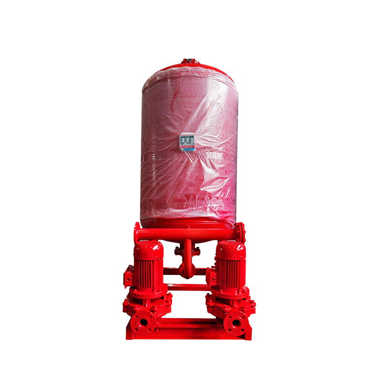 Fire Fighting Air Pressure Water Supply Equipment
The Fire Fighting Air Pressure Water Supply Equipment typically consists of a pressure tank, pump un...
-
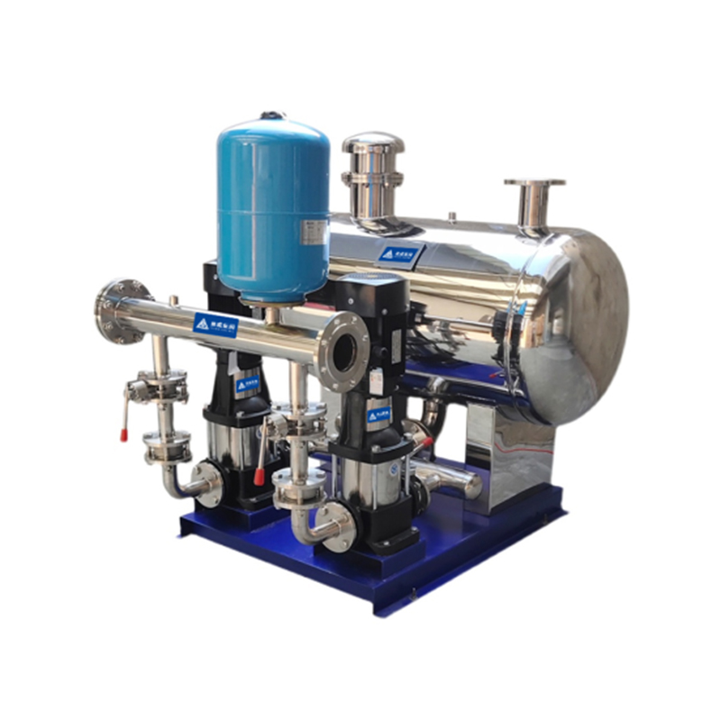 Non-Negative Pressure Water Supply Equipment
Non-negative pressure water supply equipment is a system composed of a non-negative pressure tank, p...
-
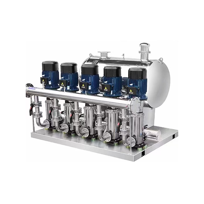 Stainless Steel Non-negative Pressure Booster Water Supply Equipment
Traditional water supply methods rely heavily on water tanks, which are typically filled with water ...
-
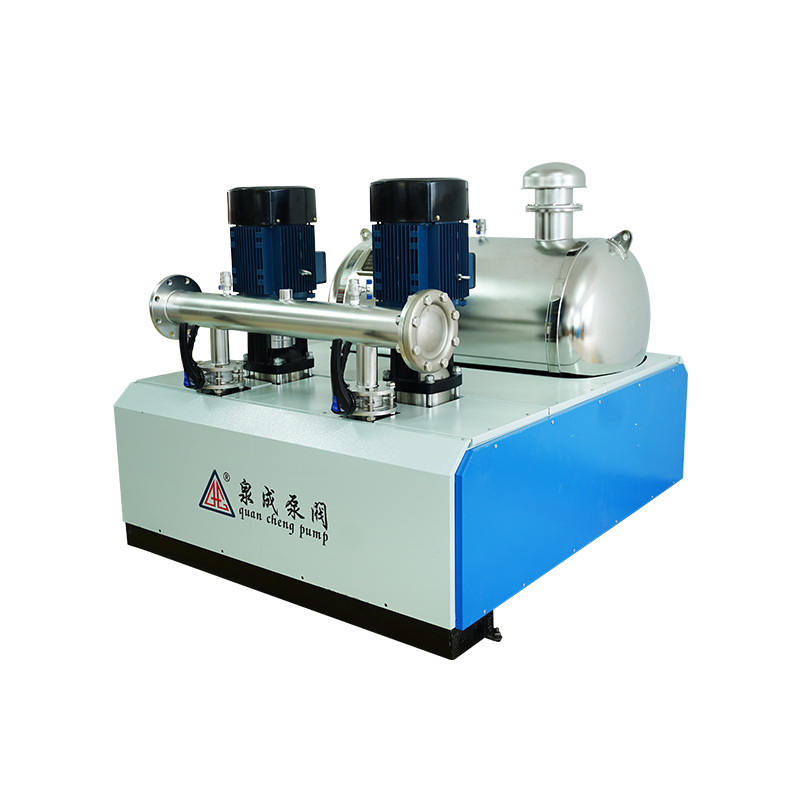 Non-negative Pressure Booster Steady Flow Water Supply Equipment
Product OverviewThe Non-negative Pressure Booster Steady Flow Water Supply Equipment uses the munici...
-
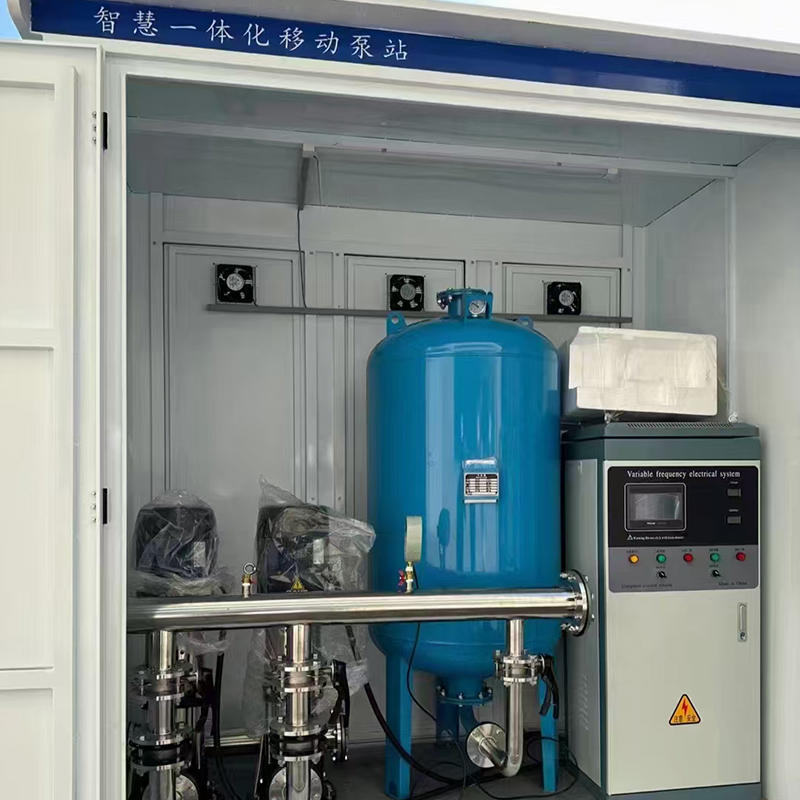 Intelligent Constant Pressure Variable Frequency Water Supply Equipment
The Intelligent Constant Pressure Variable Frequency Water Supply Equipment is a water supply system...
-
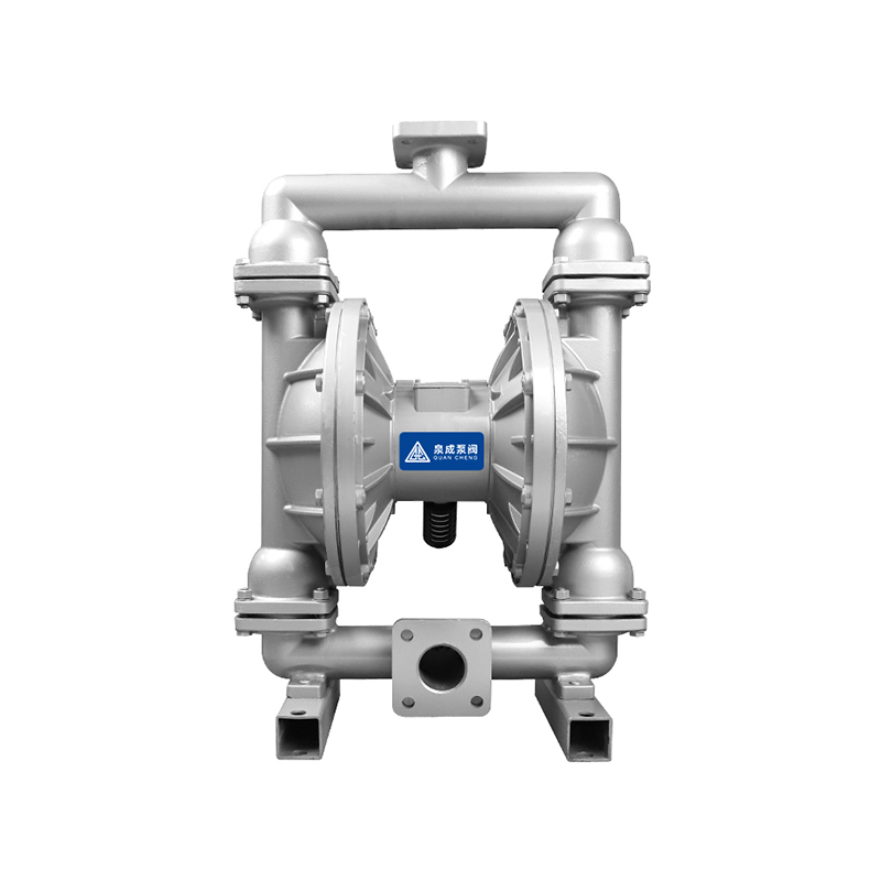 QBY Air Operated Double Diaphragm Pump
The QBY Air Operated Double Diaphragm Pump produced by our company is a new type of transport machin...
-
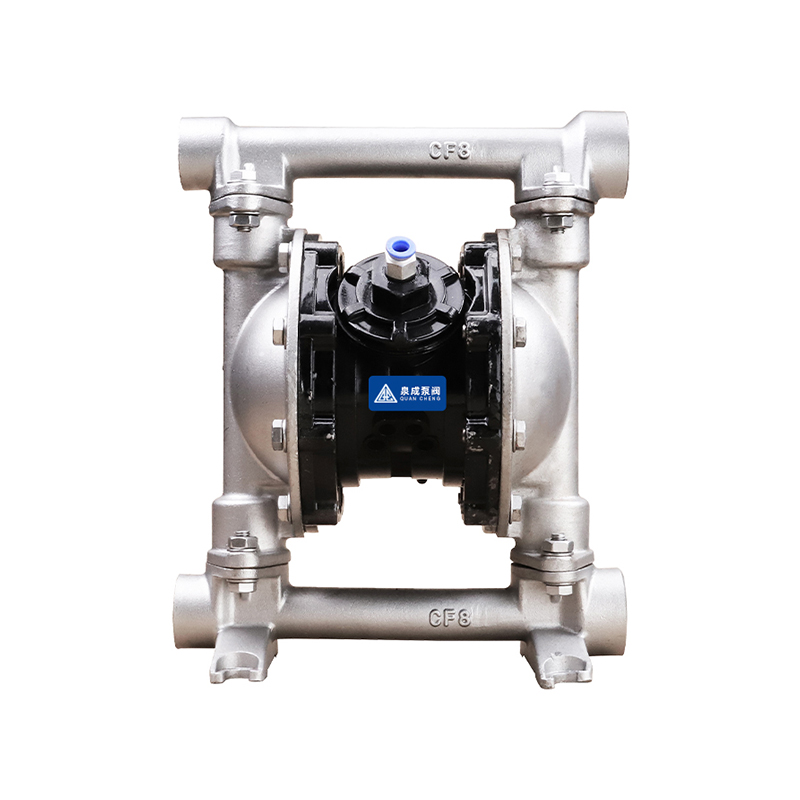 QBK Food Grade Air Operated Double Diaphragm Pump
The pneumatic diaphragm pump is a new type of conveying machinery that uses compressed air as its po...
-
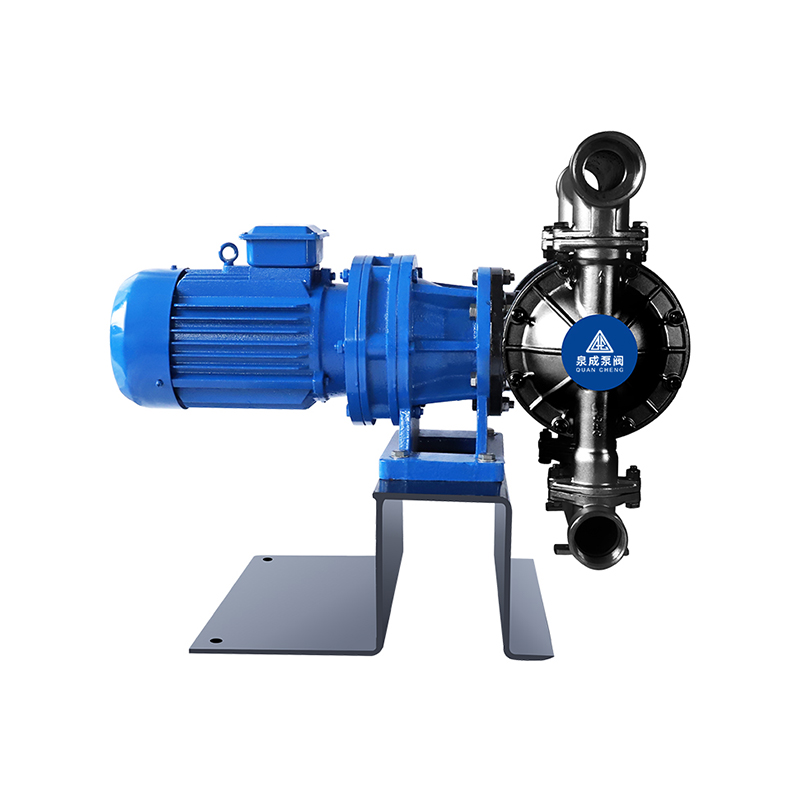 DBY Electric Stainless Steel Diaphragm Pump
The DBY Electric Stainless Steel Diaphragm Pump is a new type of pump. In recent years, due to break...
-
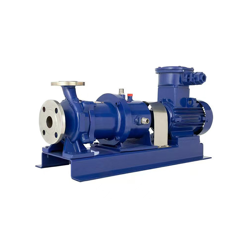 CQ Stainless Steel Magnetic Drive Pump
The CQ Stainless Steel Magnetic Drive Pump (commonly referred to as the magnetic pump) is a new prod...
-
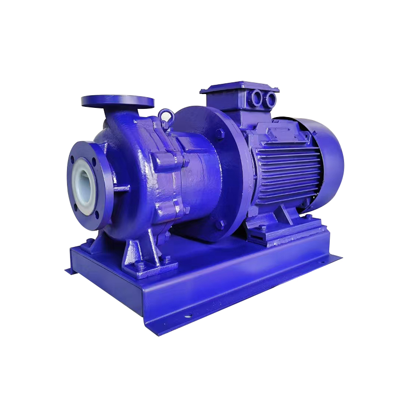 CQB-F Fluoroplastic Magnetic Drive pump
The CQB-F fluoroplastic magnetic drive pump is a new type of pump that utilizes the principles of mo...
-
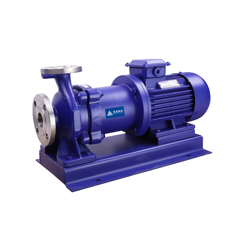 CQB Stainless Steel Magnetic Drive Centrifugal Pump
The CQB Stainless Steel Magnetic Drive Centrifugal Pump (also known as the Magnetic Pump) typically ...
-
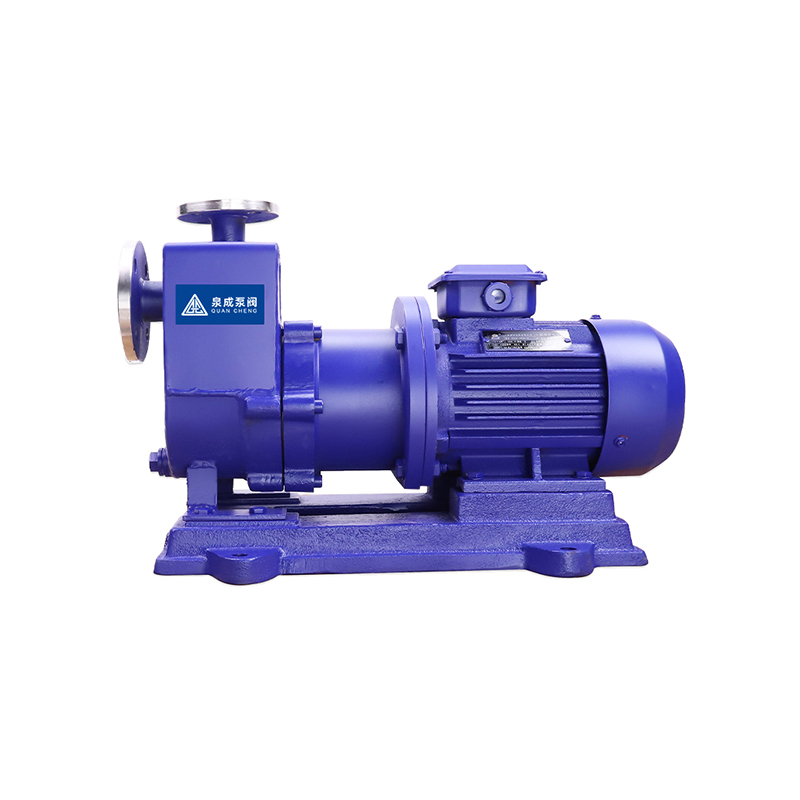 ZCQ Self-priming Magnetic Drive Pump
The ZCQ Self-priming Magnetic Drive Pump replaces the mechanical seal with a static seal, ensuring t...
-
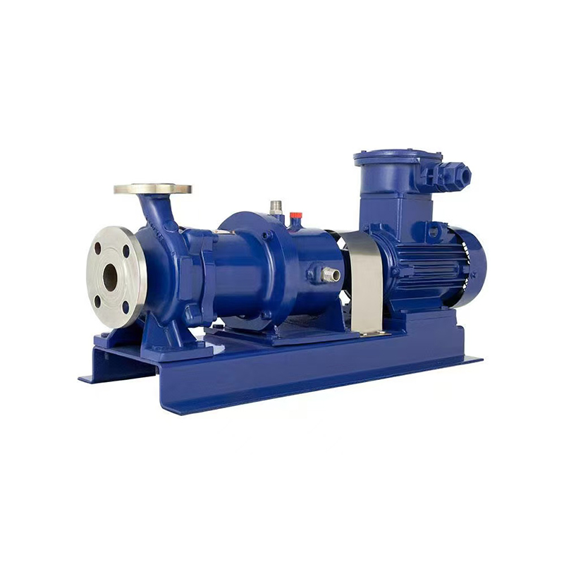 CQG High Temperature Magnetic Drive Centrifugal Pump
In response to the modernization needs of petrochemical plants in China, and to quickly adapt to ene...
-
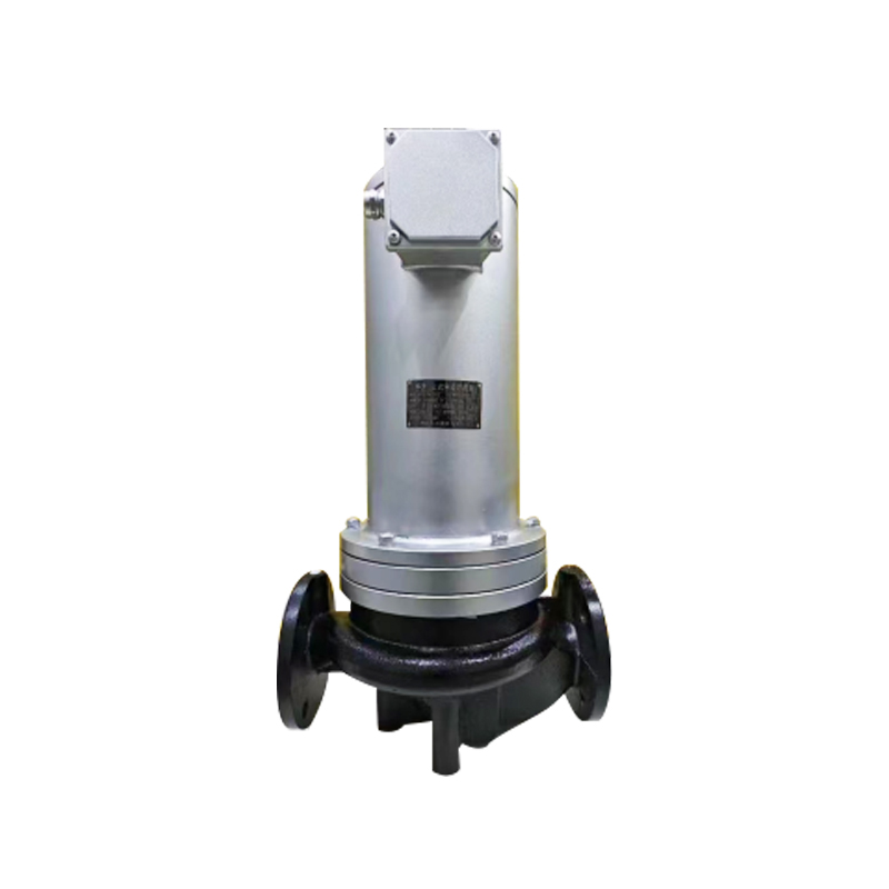 PBG Shielding Type Pipeline Pump
The PBG Shielding Type Pipeline Pump adopts advanced international shielding pump design and manufac...
-
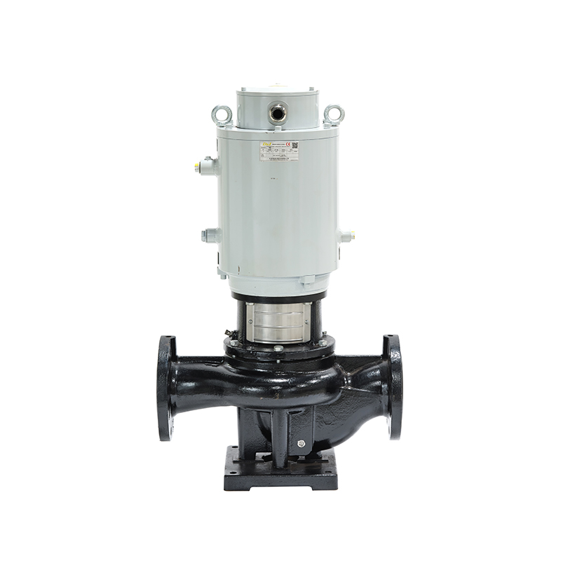 Vertical Silent Pipeline Booster Pump
The Vertical Silent Pipeline Booster Pump is a single-stage centrifugal pump, designed with advanced...
-
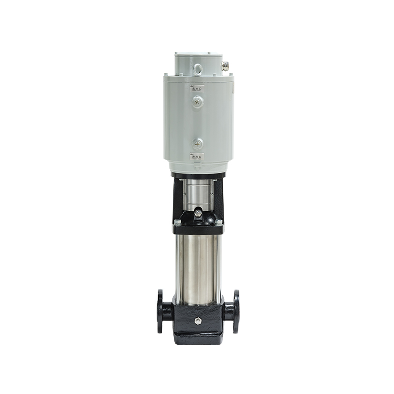 Stainless Steel Vertical Silent Multistage Pump
The Stainless Steel Vertical Silent Multistage Pump is a new generation of high-efficiency, non-self...
-
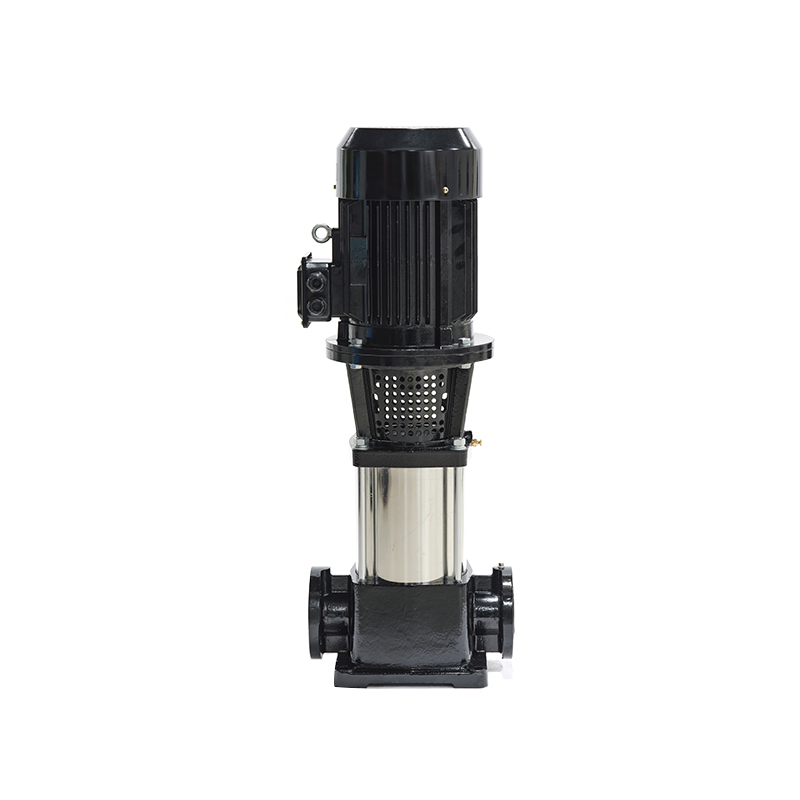 GDL Vertical Multistage Pipeline Pump
The GDL Vertical Multistage Pipeline Pump is a newly developed pump model, characterized by energy e...
-
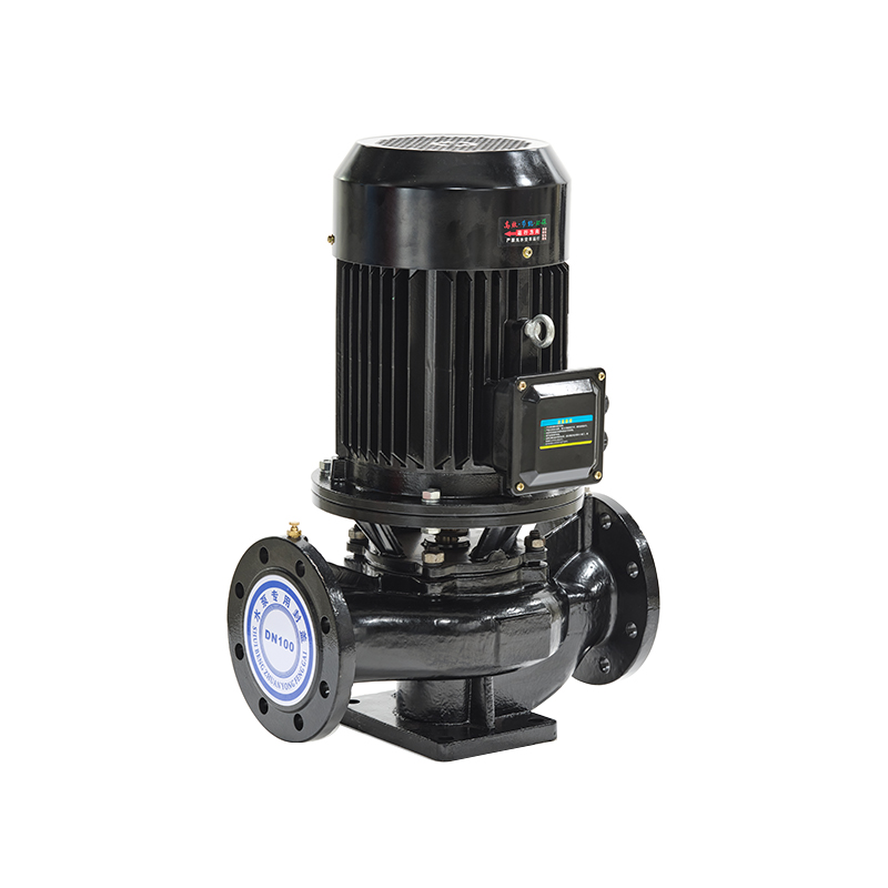 ISG Single Stage Single Suction Vertical Pipeline Centrifugal Pump
The ISG Single Stage Single Suction Vertical Pipeline Centrifugal Pump is developed by our technical...
-
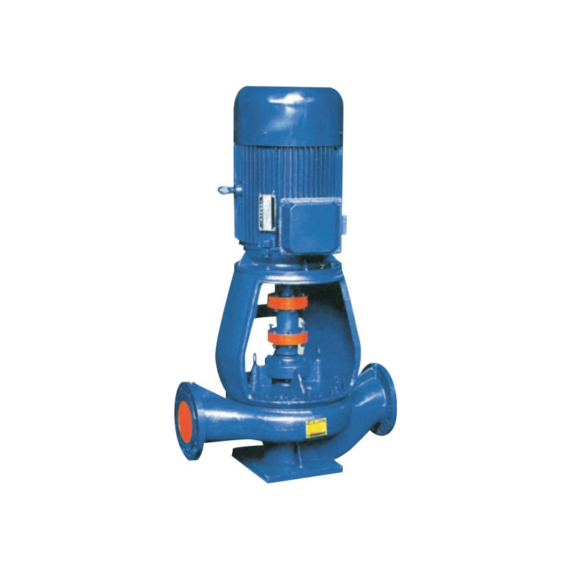 ISGB Easy-disassemble Vertical Pipeline Centrifugal Pump
The ISGB Easy-disassemble Vertical Pipeline Centrifugal Pump is an innovative and advanced product d...
-
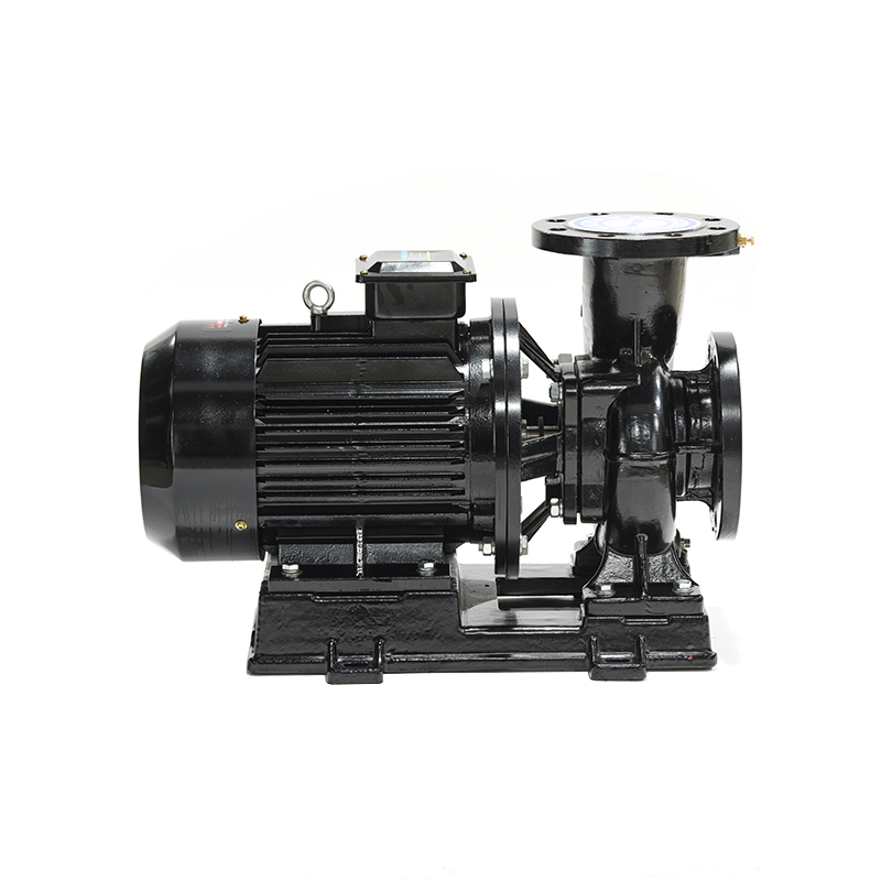 ISW Horizontal Centrifugal Pump
-
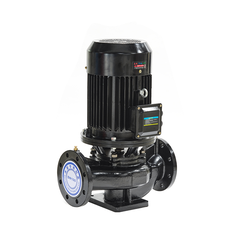 ISGD Low-speed Centrifugal Pump
The ISGD Low-speed Centrifugal Pump is designed and manufactured based on the ISG single-stage singl...
-
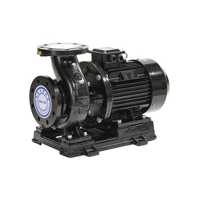 ISWD High Efficiency Low Speed Centrifugal Pump
The ISWD High Efficiency Low Speed Centrifugal Pump is developed based on the ISW Horizontal Centrif...
-
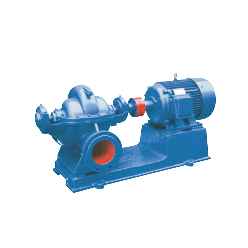 S/SH Single Stage Double Suction Centrifugal Pump
The S-type is a new energy-saving horizontal single-stage double-suction centrifugal pump designed f...
-
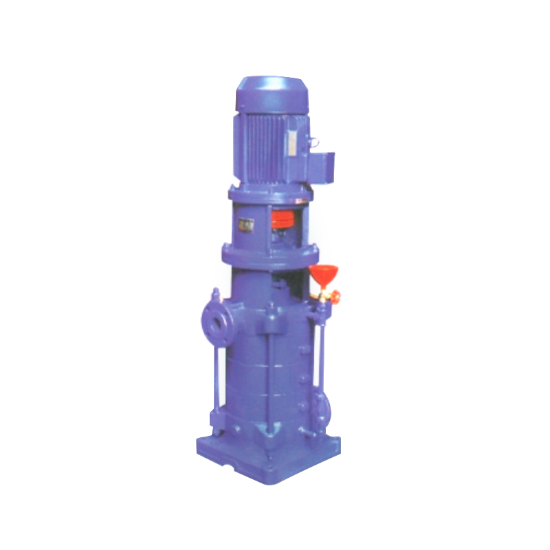 DL/DLR Vertical Multistage Centrifugal Water Pump
The DL/DLR Vertical Multistage Centrifugal Pump is an optimized design and manufacturing improvement...
-
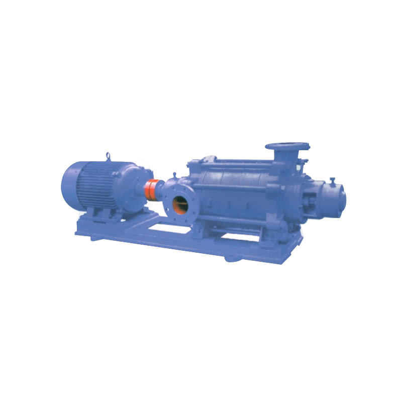 TSWA Horizontal Multistage Centrifugal Pump
The TSWA Horizontal Multistage Centrifugal Pumps are energy-saving products developed and manufactur...
-
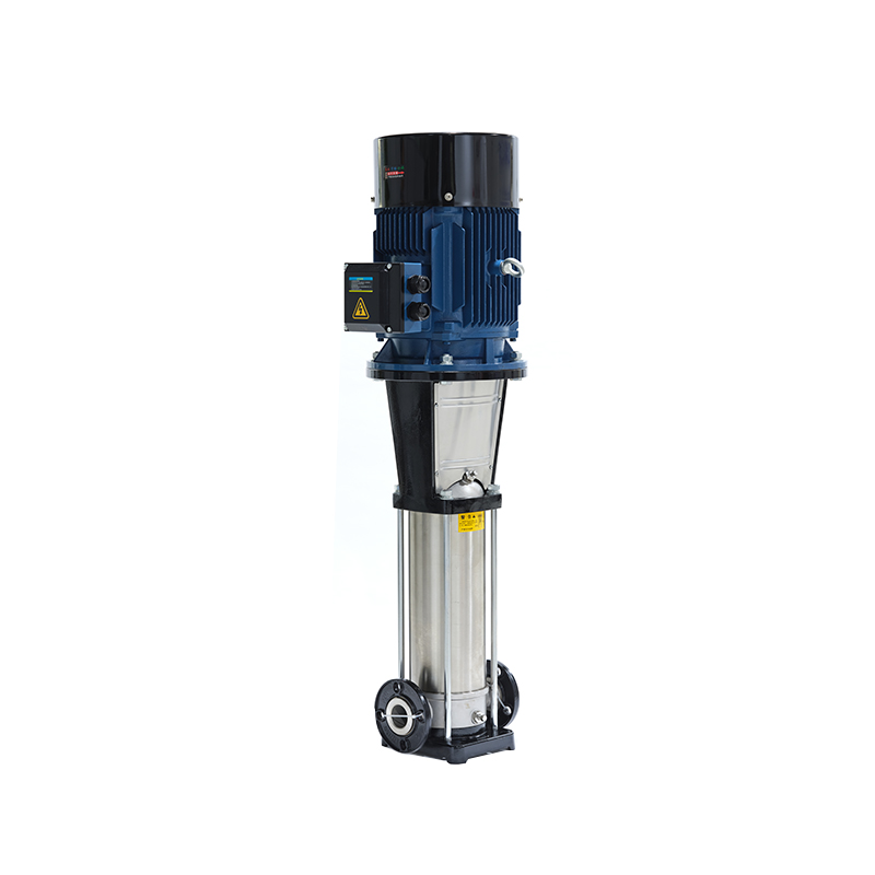 CDL/CDLF Light Vertical Multistage Centrifugal Pump
The CDL/CDLF is a type of vertical, non-self-priming, multistage centrifugal pump, driven by a stand...
-
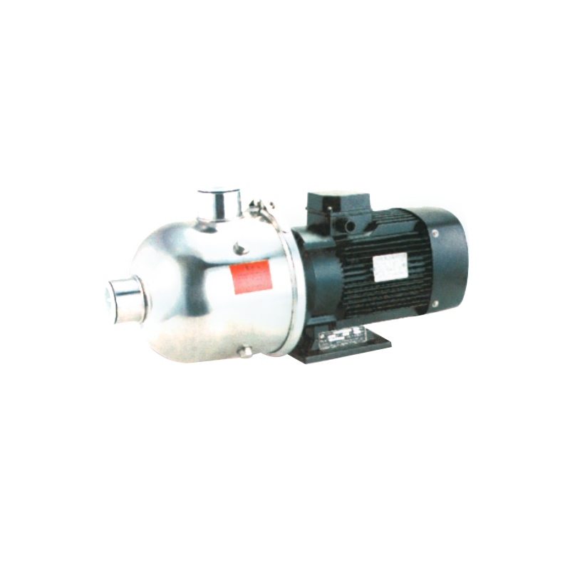 CHL Horizontal Stainless Steel Multistage Centrifugal Pump
The CHL Horizontal Stainless Steel Multistage Centrifugal Pump is equipped with a horizontal extende...
-
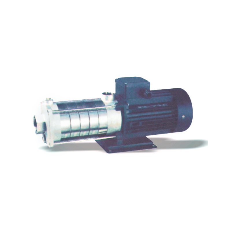 CHDF Segmental Light Horizontal Multistage Centrifugal Pump
The CHDF Segmental Light Horizontal Multistage Centrifugal Pump is equipped with a horizontal extend...
-
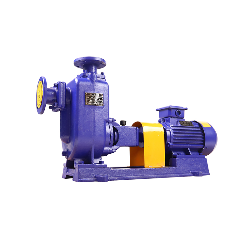 ZX Self-Priming Centrifugal Water Pump
The ZX Self-Priming Water Pump is a type of self-priming centrifugal pump. It features a compact str...
-
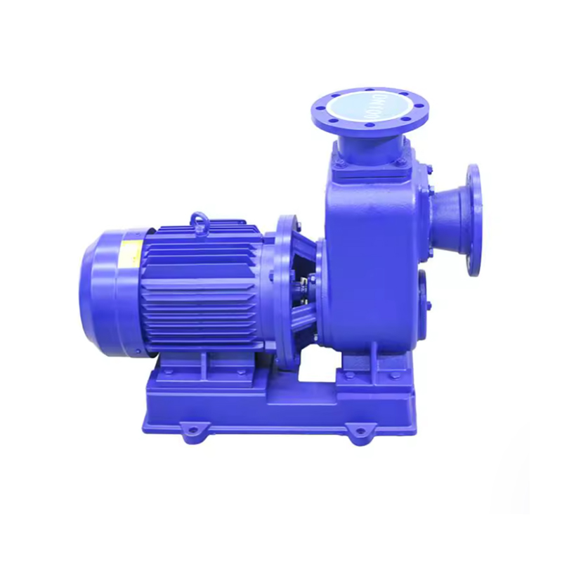 ZXL Direct-Connected Self-Priming Centrifugal Pump
The ZXL Direct-Connected Self-Priming Centrifugal Pump system is a new product developed by our comp...
-
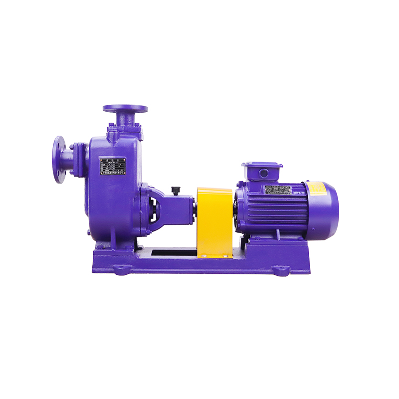 ZW Self-Priming Non-clogging Sewage Water Pump
The ZW self-priming non-clogging sewage pump, also known as a solid-liquid pump or trash pump, featu...
-
ZWL Direct Connected Non-clogging Self-Priming Sewage Pump
The ZWL Direct Connected Non-clogging Self-Priming Sewage Pump integrates self-priming and non-clogg...
-
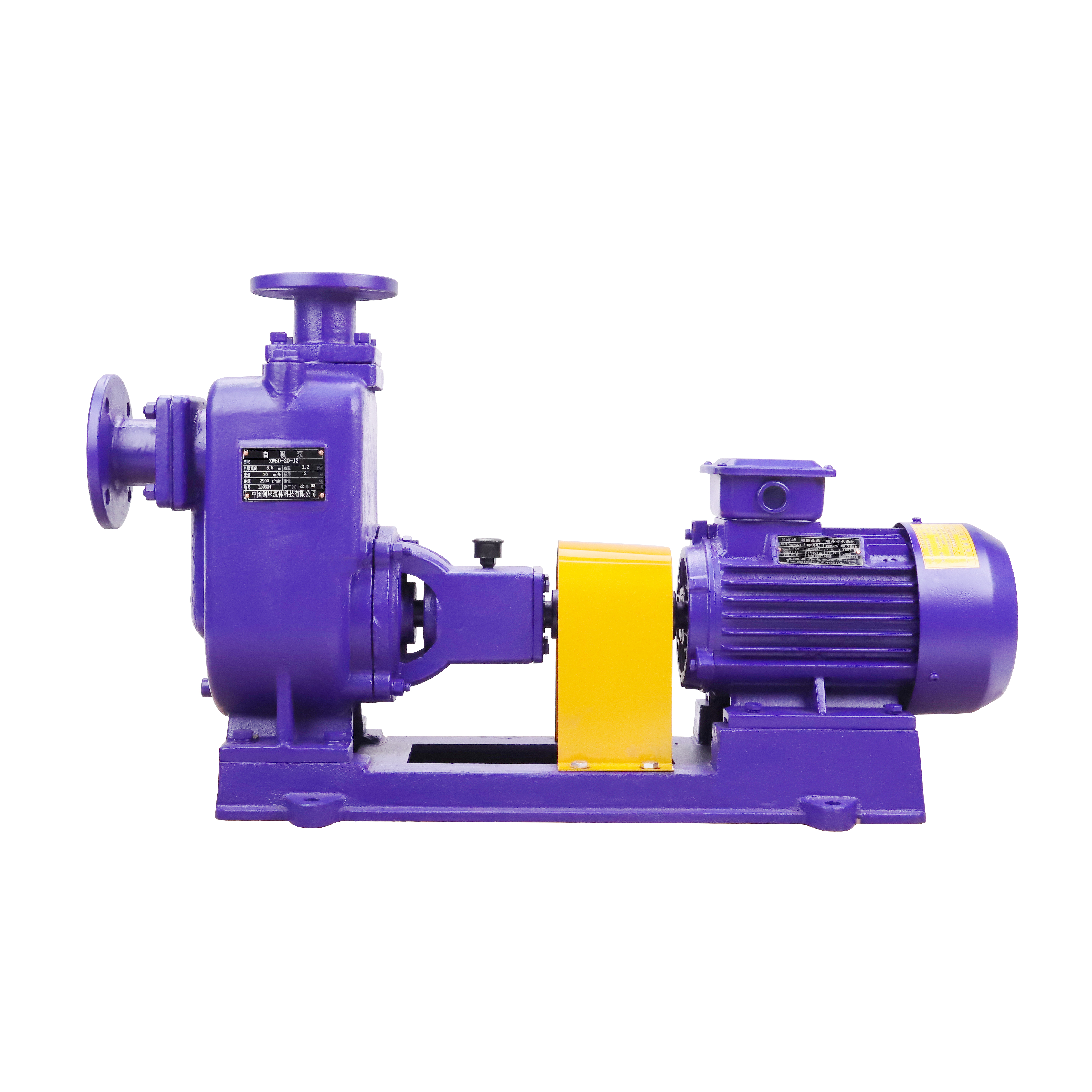 CYZ-A Self-priming Centrifugal Oil Transfer Pump
The CYZ-A Self-priming Centrifugal Oil Transfer Pump is a newly developed pump product, designed aft...
-
CYZL-A Direct-Connected Self-priming Centrifugal Oil Pump
The CYZL-A Direct-Connected Self-priming Centrifugal Oil Pump is our latest pump product, developed ...
-
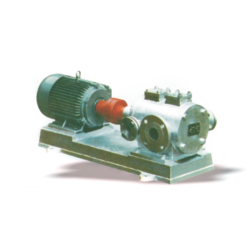 LQG Three-screw Pump (Heat-preserving Bitumen Pump)
The LQG Three-screw Pump (Heat-preserving Bitumen Pump), also known as the LQG asphalt three-screw p...
-
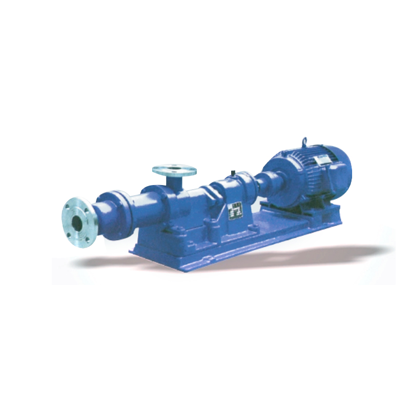 I-1B Thick Slurry Screw Pump
The I-1B Thick Slurry Screw Pump is a single-screw positive displacement pump. The pump utilizes the...
-
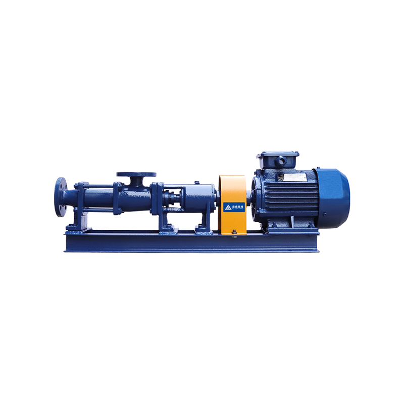 G Stainless Steel Single Screw Pump
The G Stainless Steel Single Screw Pump is a newly designed pump based on the principle of rotary me...
-
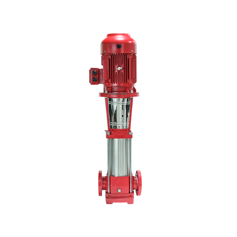 XBD-L Vertical Fire Fighting Pump
The XBD-L vertical fire fighting pump is a vertical single-suction multi-stage centrifugal pump desi...
-
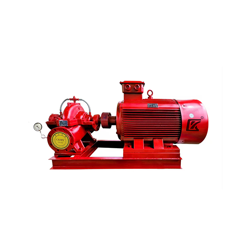 XBD-W Horizontal Multistage Fire Pump
The XBD-W Horizontal Multistage Fire Pump is a newly developed, energy-efficient series product with...
-
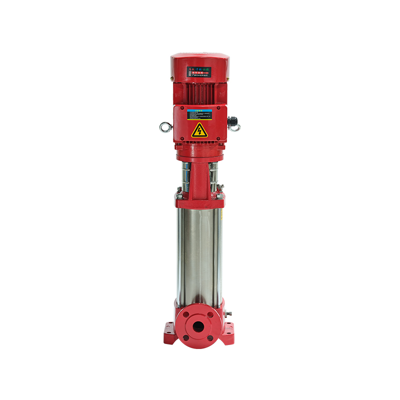 XBD-(I) Vertical Fire Pump Pipeline Pump
The XBD-(I) Vertical Fire Pump Pipeline Pump is a next-generation product developed based on the exi...
-
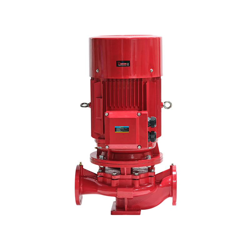 XBD-ISG Vertical Single-stage Fire Pump
The XBD-ISG Vertical Single-stage Fire Pump is designed to transport clean water without solid parti...
-
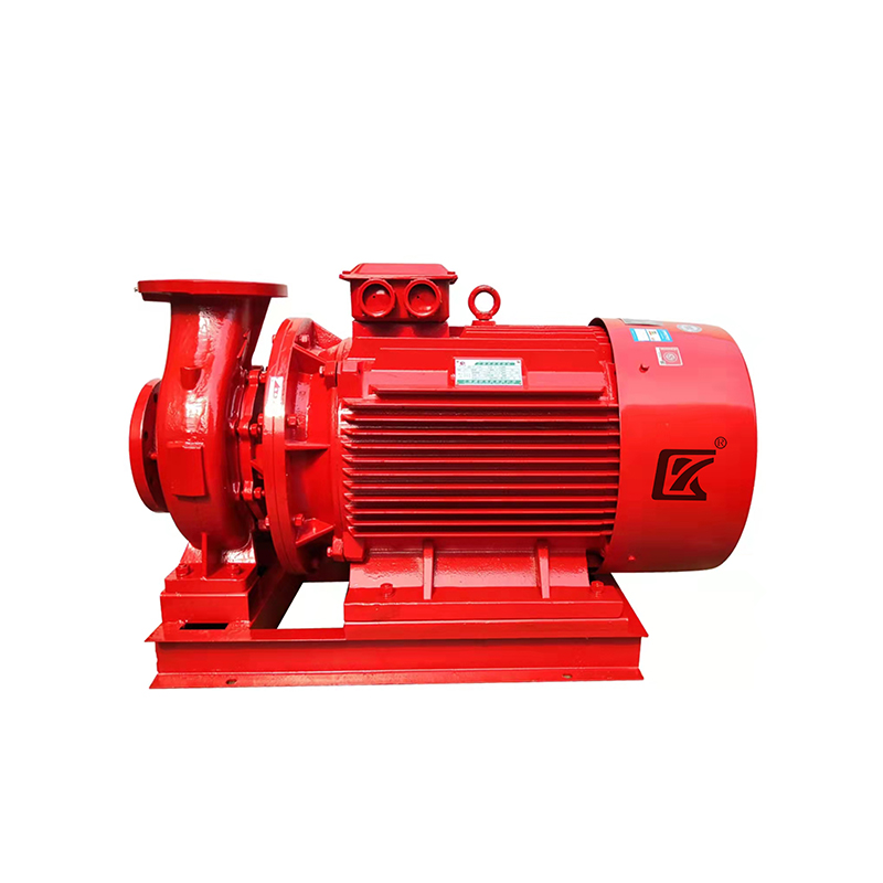 XBD-ISW Horizontal Fire Fighting Pump
The XBD-ISW single-suction multi-stage sectional fire-fighting pump is designed for transporting cle...
-
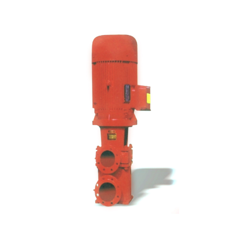 XBD-HL Vertical Fire Constant Pressure Tangent Pump
The XBD-HL Vertical Fire Constant Pressure Tangent Pump (Vertical) is a third-generation advanced pr...
-
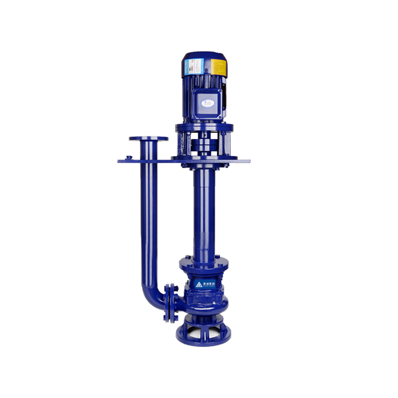 YW Vertical Semi-submersible Sewage Pump
The YW series vertical semi-submersible sewage pump is a new generation of pump products developed b...
-
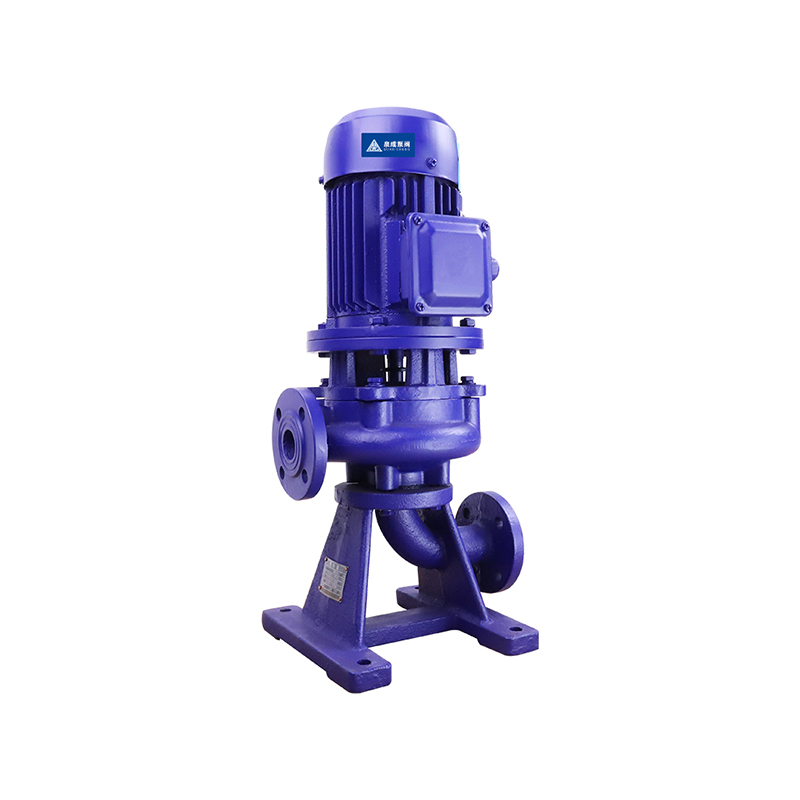 LW (WL) Non-clogging Vertical Sewage Pump
The LW non-clogging vertical sewage pump is a next-generation pump product successfully developed by...
-
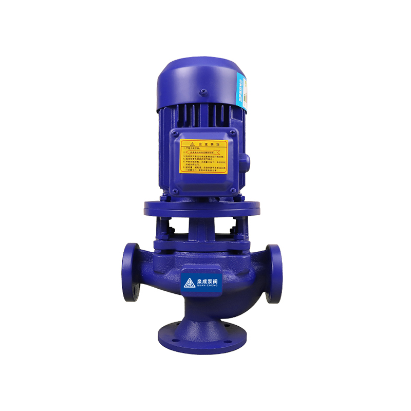 GW Efficiently Pipeline Non-clogging Sewage Pump
The GW Efficiently Pipeline Non-clogging Sewage Pump is a new generation of pump products developed ...
-
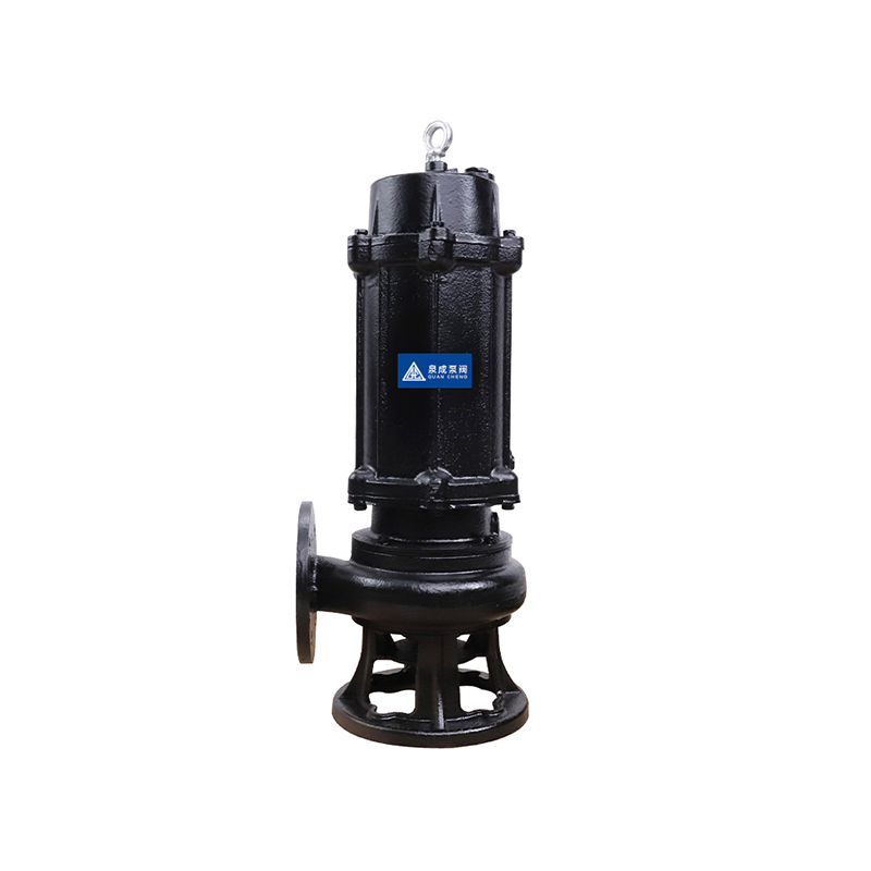 JYWQ Automatic Mixing Sewage Pump
The JYWQ Series Automatic Mixing Sewage Pump is an advanced version of the standard sewage pump, inc...
-
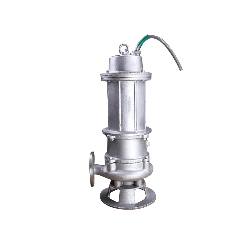 JPWQ Automatic Stirring Sewage Pump with Stainless Steel Jacket
The JPWQ series Automatic Stirring Sewage Pump is an enhanced version of the standard sewage pump, f...
-
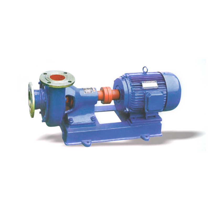 PWF Corrosion-resistant Centrifugal Sewage Pump
The PWF Corrosion-resistant Centrifugal Sewage Pump is designed to transport sewage with temperature...
-
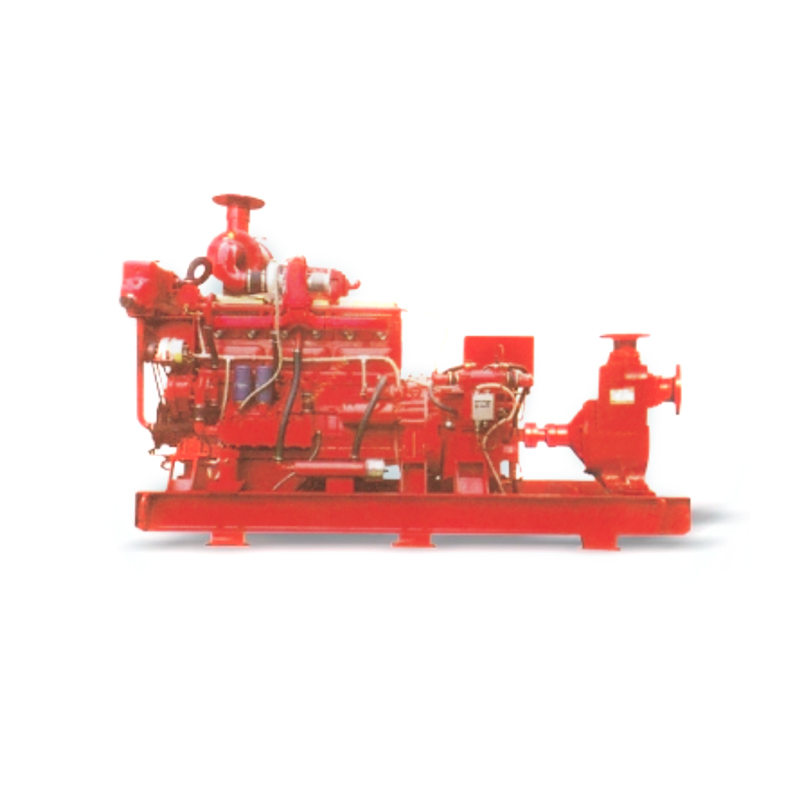 XBC-ZX Horizontal Diesel Engine Fire Pump Unit
The XBC-ZX Horizontal Diesel Engine Fire Pump Unit is a new type of firefighting equipment developed...
-
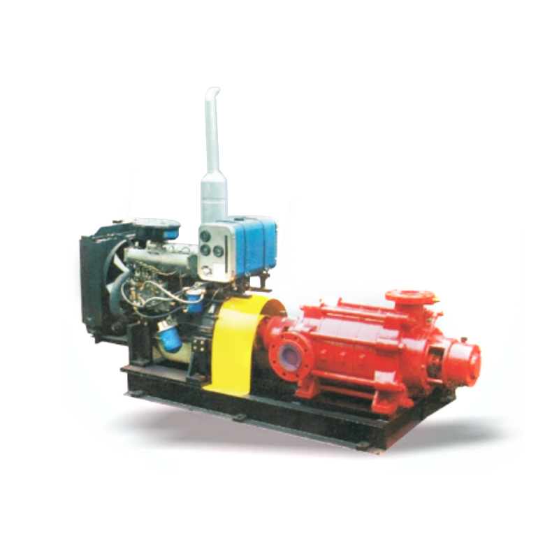 XBC-TSWA Diesel Engine Fire Pump Set
The XBC-TSWA Diesel Engine Fire Pump Set, as a fixed fire extinguishing equipment, has been widely u...
-
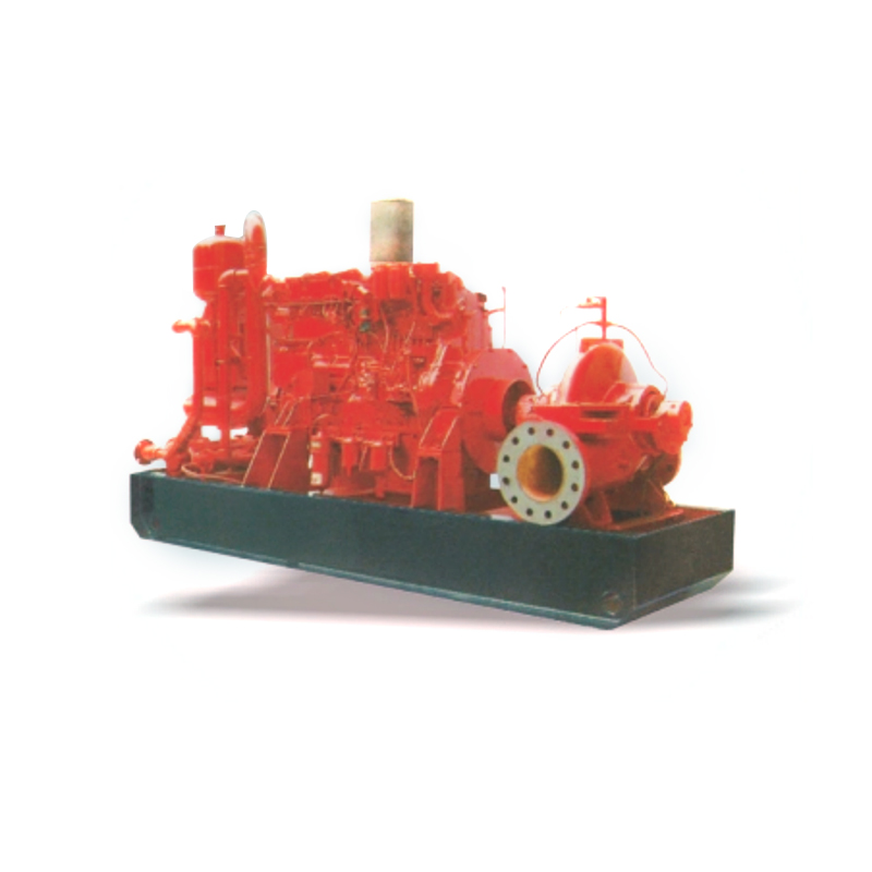 XBC-SOW Diesel Engine Fire Fighting Pump Unit
The XBC-SOW Diesel Engine Fire Fighting Pump Unit is renowned for its high flow rate and is widely u...
-
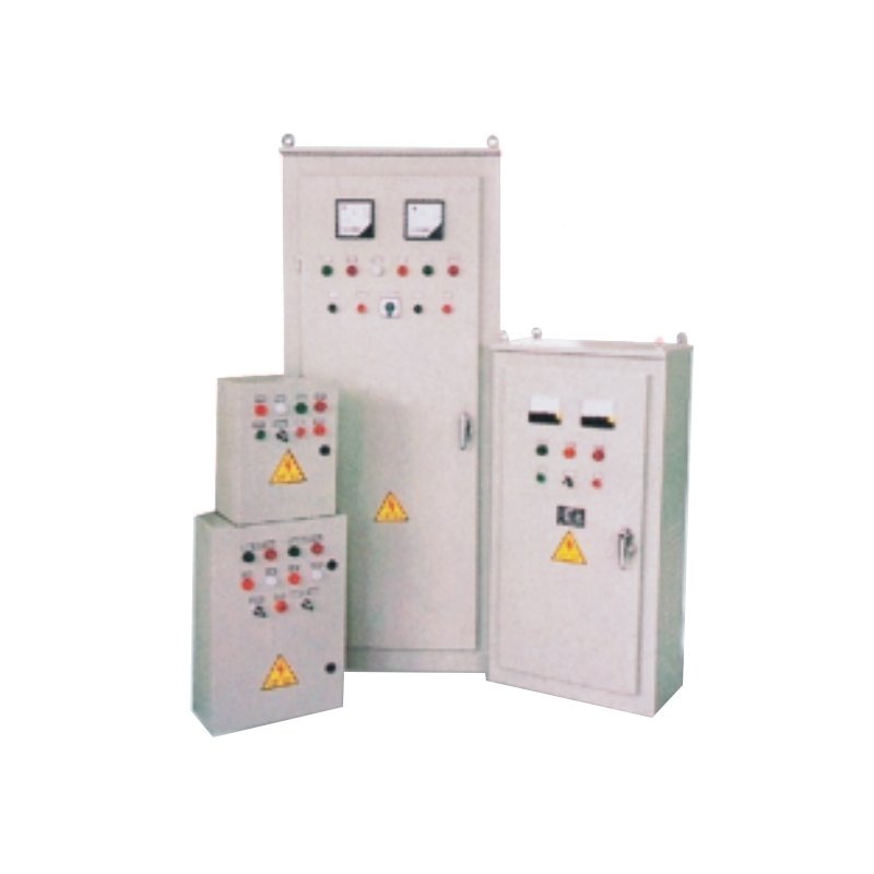 JJ1 Self-Coupling Start Decompression Control Cabinet
The JJ1 series Self-Coupling Start Decompression Control Cabinet is designed and manufactured with m...
-
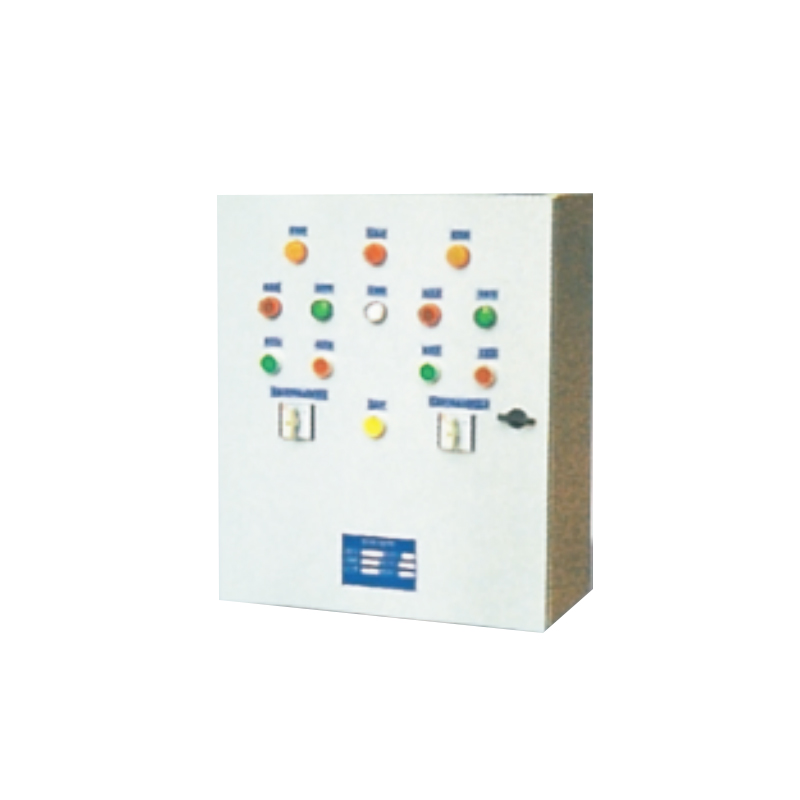 QZD Water Pump Control Cabinet
The QZD Water Pump Control Cabinet produced by our company are innovative automatic control device f...
-
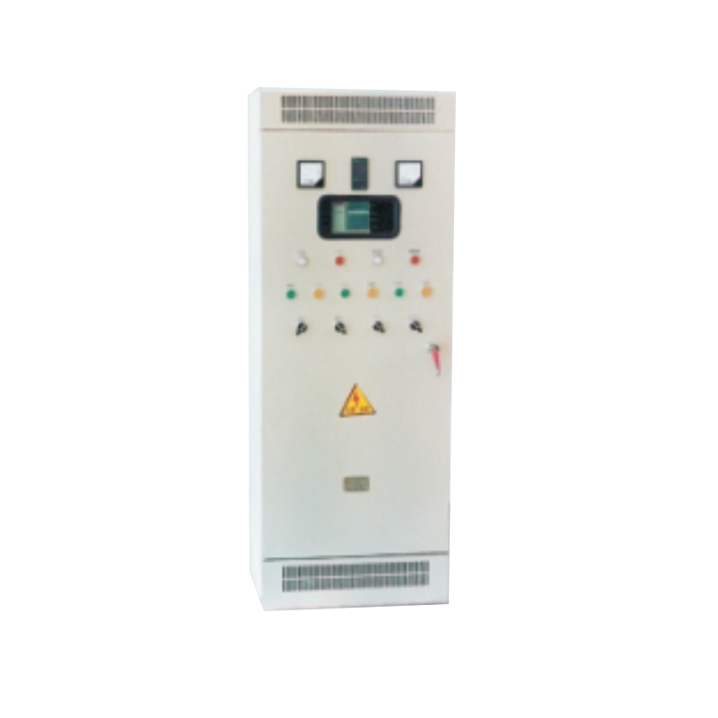 Frequency Conversion Speed Control Cabinet
The Frequency Conversion Speed Control Cabinet is designed for three-phase asynchronous or synchrono...
-
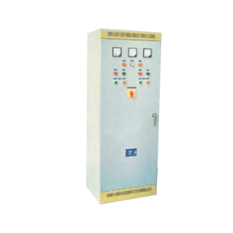 Auto-transformer Start Decompression Control Cabinet
The Auto-transformer Start Decompression Control Cabinet is a next-generation energy-efficient water...
-
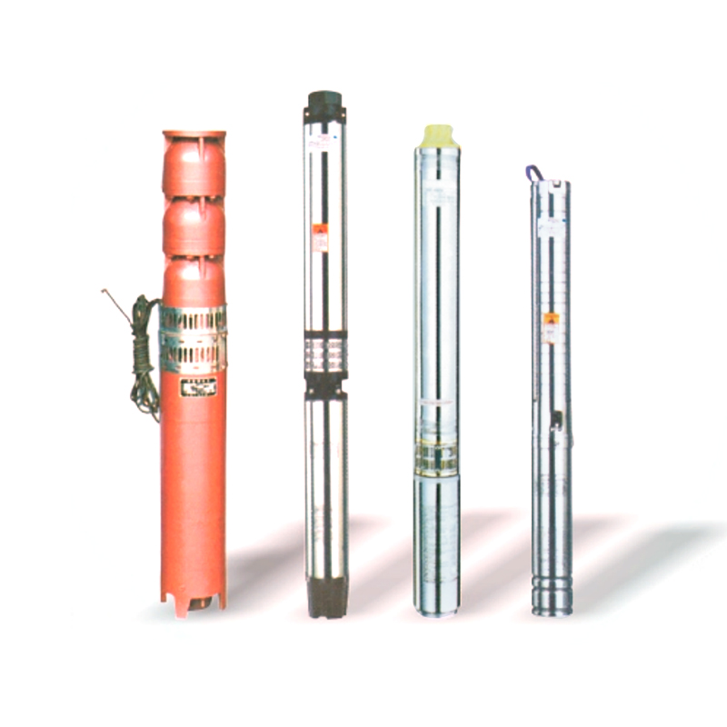 QJ Stainless Steel Deep Well Submersible Electric Pump
The QJ Stainless Steel Deep Well Submersible Electric Pump is a water lifting device where the motor...
-
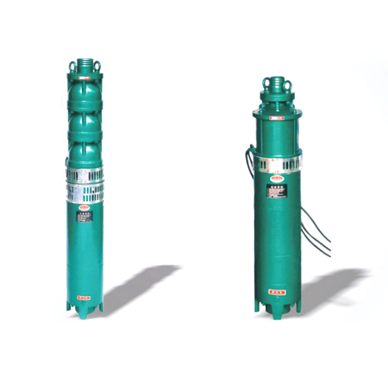 QS Small Water Filled Submersible Pump
The QS Small Water Filled Submersible Pump (referred to as the submersible pump) is an integrated el...
-
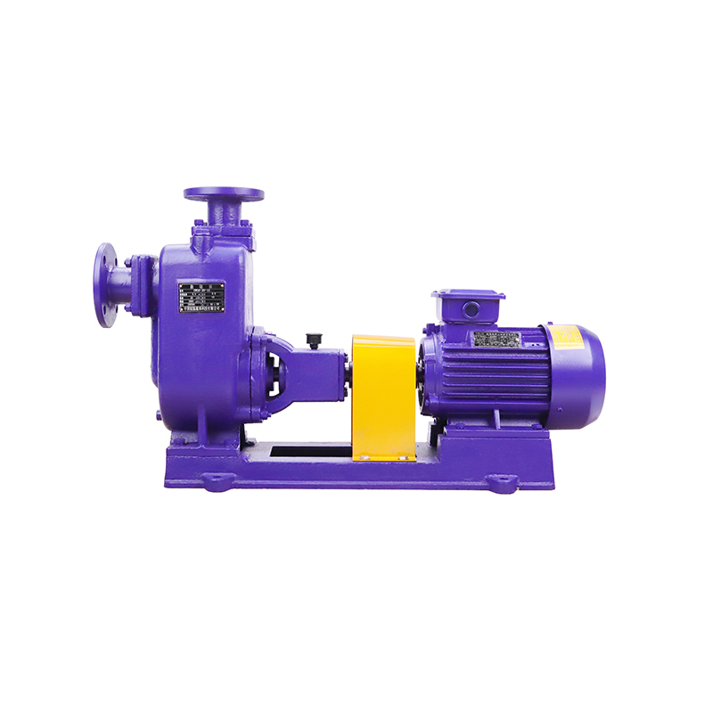 ZX(ZXL)/ZW(ZWL) Self-Priming Centrifugal Pump
The ZX(ZXL)/ZW(ZWL) Self-Priming Centrifugal Pumps are energy-efficient products developed by incorp...
-
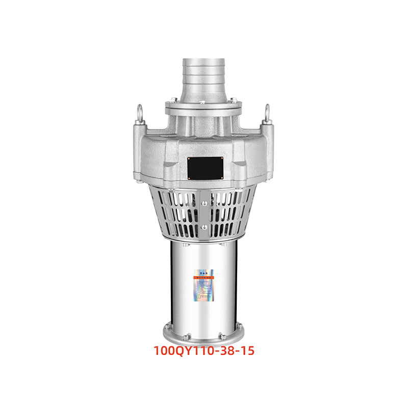 QY Oil Filled Submersible Electric Pump
The QY Oil-Filled Submersible Electric Pump (referred to as the submersible pump) is a power drainag...
-
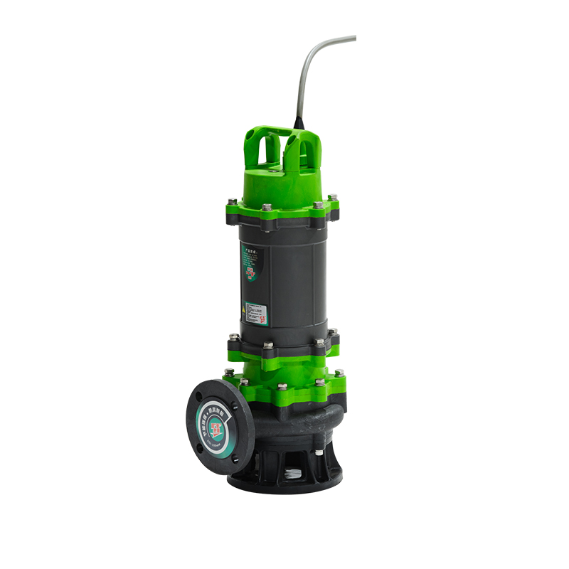 WQF High-Polymer Corrosion-Resistant Submersible Pump
The WQF High-Polymer Corrosion-Resistant Submersible Pump is a specialized product developed using i...
-
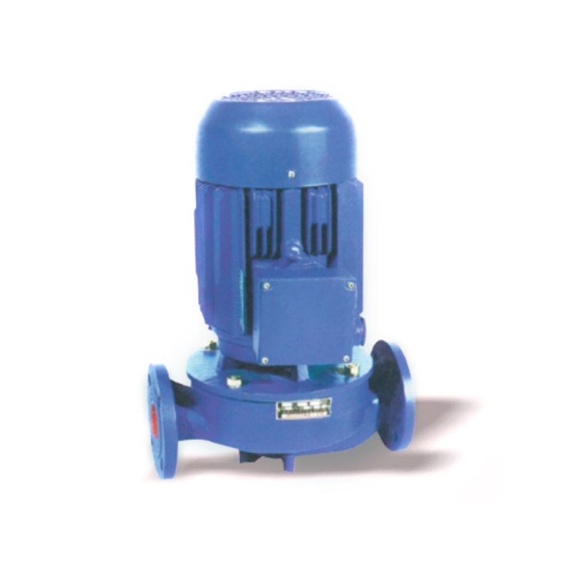 SG Vertical Pipeline Booster Pump
The SG Vertical Pipeline Booster Pumps are designed to address low pipeline pressure and provide eff...
-
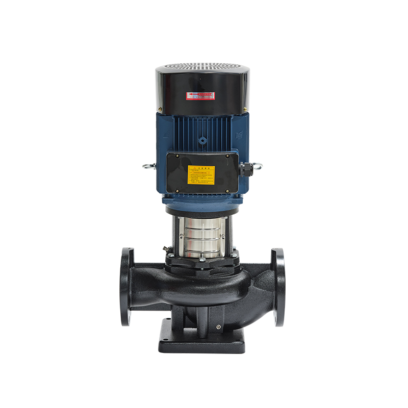 TD Vertical Pipeline Circulation Pump
The TD Vertical Pipeline Circulation Pump is a single-stage centrifugal pump that adopts advanced hy...
-
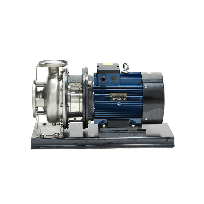 ZS Stainless Steel Horizontal Single-stage Centrifugal Pump
The ZS Stainless Steel Horizontal Single-stage Centrifugal Pump is made using advanced processes suc...
-
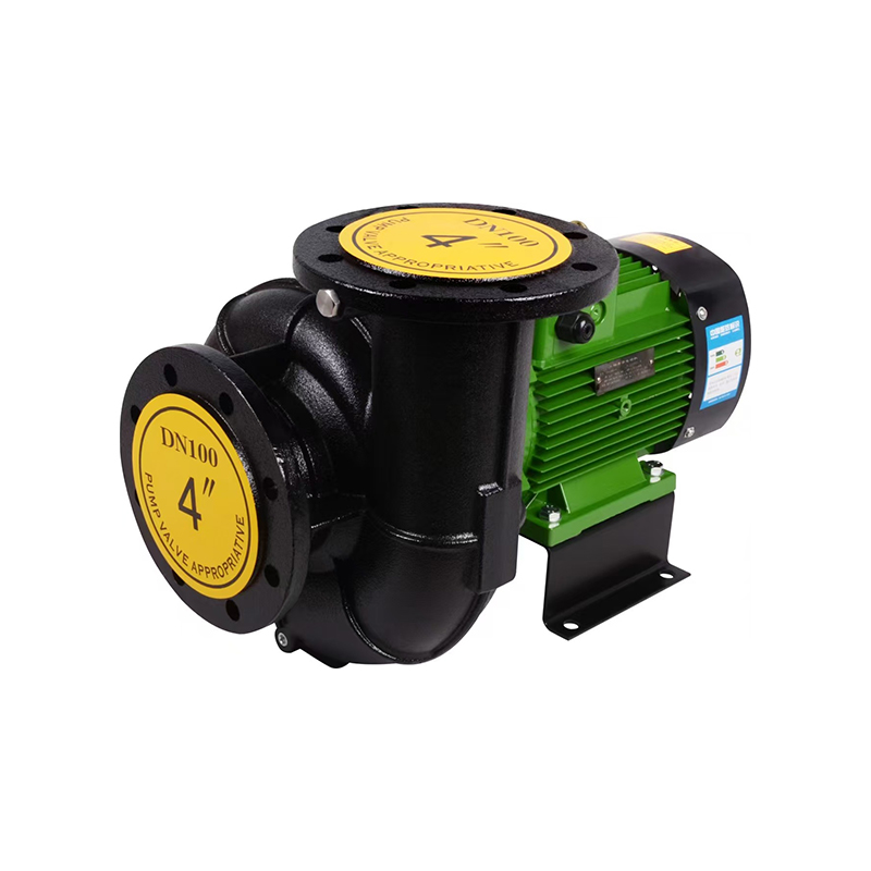 CWT(WLT) Horizontal Cooling Tower Specialized Pump
The CWT(WLT) Horizontal Cooling Tower Specialized Pump is a high-flow, low-head pump with reliable p...
-
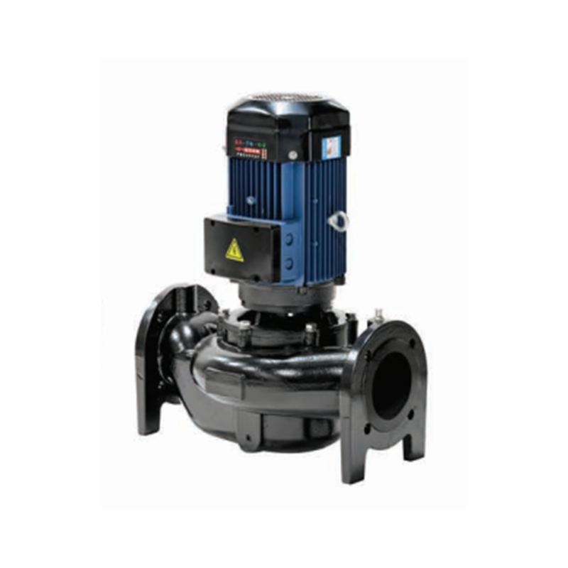 LLT Vertical Cooling Tower Pipeline Pump
TheLLT Vertical Cooling Tower Pipeline Pump is a large flow, low head pump known for its reliability...
-
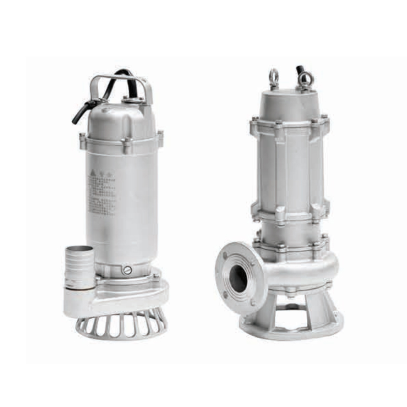 WQ Non-clogging Submersible Sewage Pump
The WQ Non-clogging Submersible Sewage Pump is primarily used in municipal engineering, industry, ho...
-
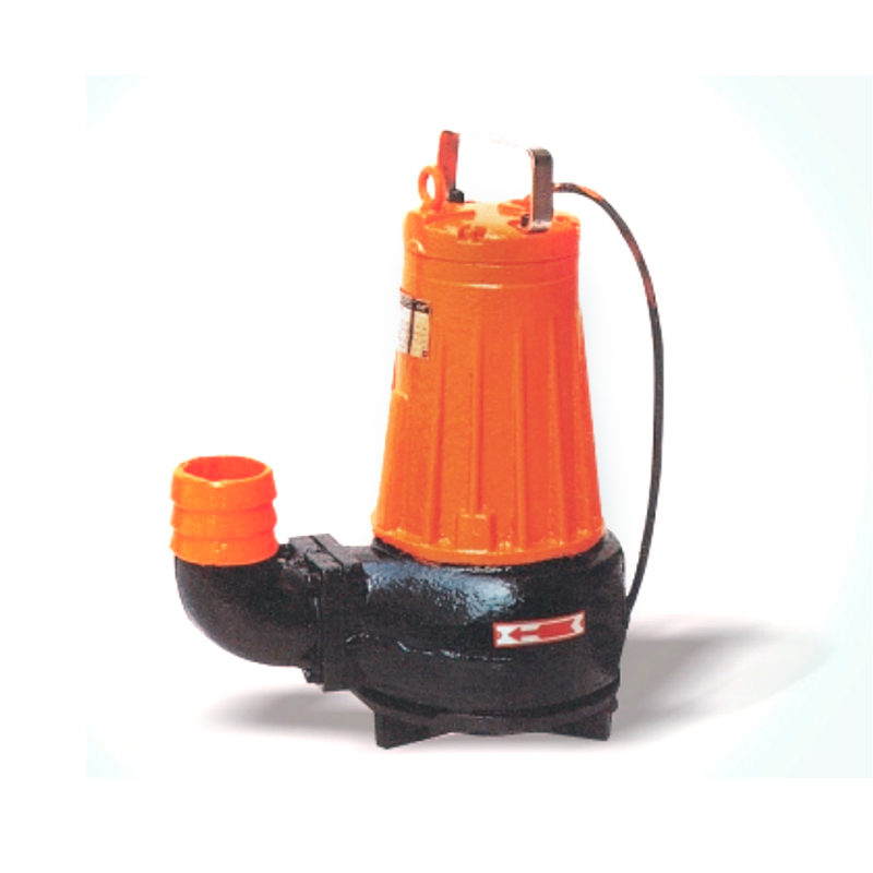 AS AV Non-clogging Type Submersible Sewage Pump
The AS Series Non-clogging Type Submersible Sewage Pump adopts advanced technology from Germany's AB...
-
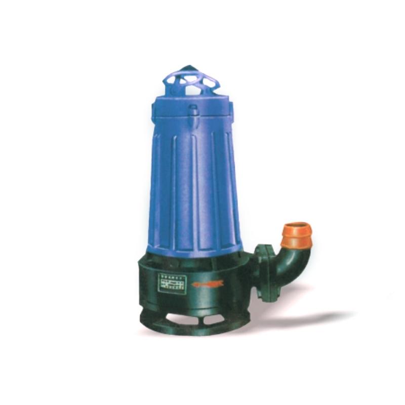 WQK/QG Belt Cutting Device Submersible Sewage Pump
The WQK/QG Belt Cutting Device Submersible Sewage Pump features exceptional sewage discharge capabil...
-
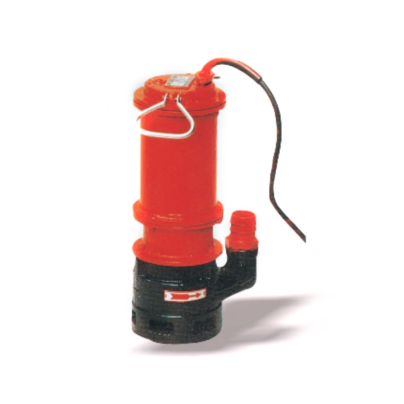 WQX Submersible Sewage Pump with Cutting Device
The WQX series submersible sewage pump is primarily used for draining domestic wastewater, sewage, h...
-
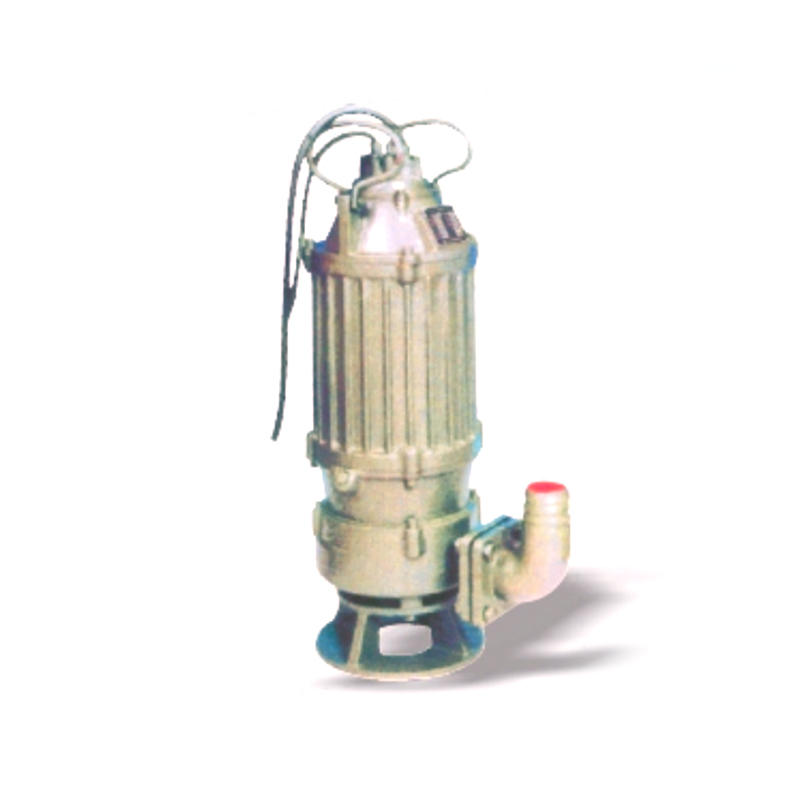 WQD Cutting Blade Electric Submersible Sewage Pump
The WQD Cutting Blade Electric Submersible Sewage Pump is a new type of sewage equipment designed an...
-
QW Non-Clogging Submersible Sewage Pump
The QW Series Non-Clogging Submersible Sewage Pump is a new generation of pump products developed ba...
-
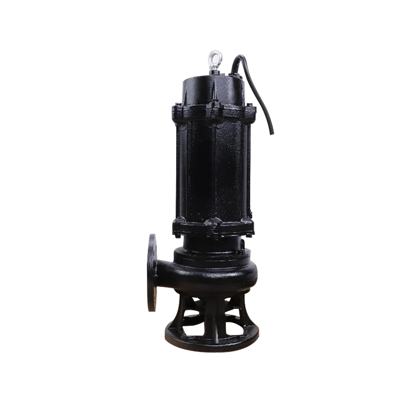 WQ Auto Coupled Submersible Sewage Pump
The WQ Auto Coupled Submersible Sewage Pump is an advanced, next-generation pump designed by incorpo...
-
 2X Two Stage Rotary Vane Vacuum Pump
The 2X Two Stage Rotary Vane Vacuum Pump features a two-stage structure. Its operating performance i...
-
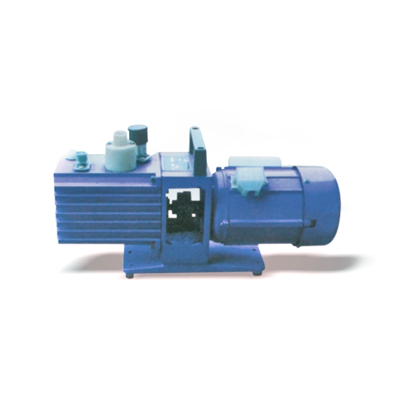 2XZ Two Stage Direct Drive Rotary Vane Vacuum Pump
The 2XZ vacuum pump features a two-stage direct-drive structure, with its performance divided into t...
-
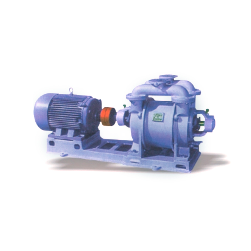 SK Water Ring Vacuum Pump
The SK Water Ring Vacuum Pumps and Compressors are designed to extract or compress air and other non...
-
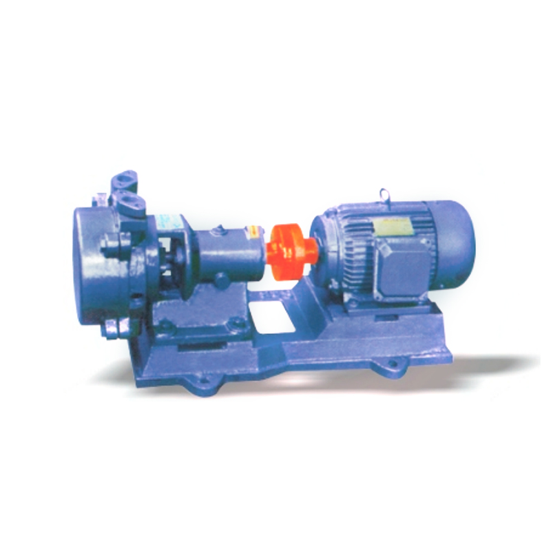 SZB Cantilever Water Ring Vacuum Pump
The SZB series vacuum pump is a cantilever liquid ring vacuum pump designed for the suction of air o...
-
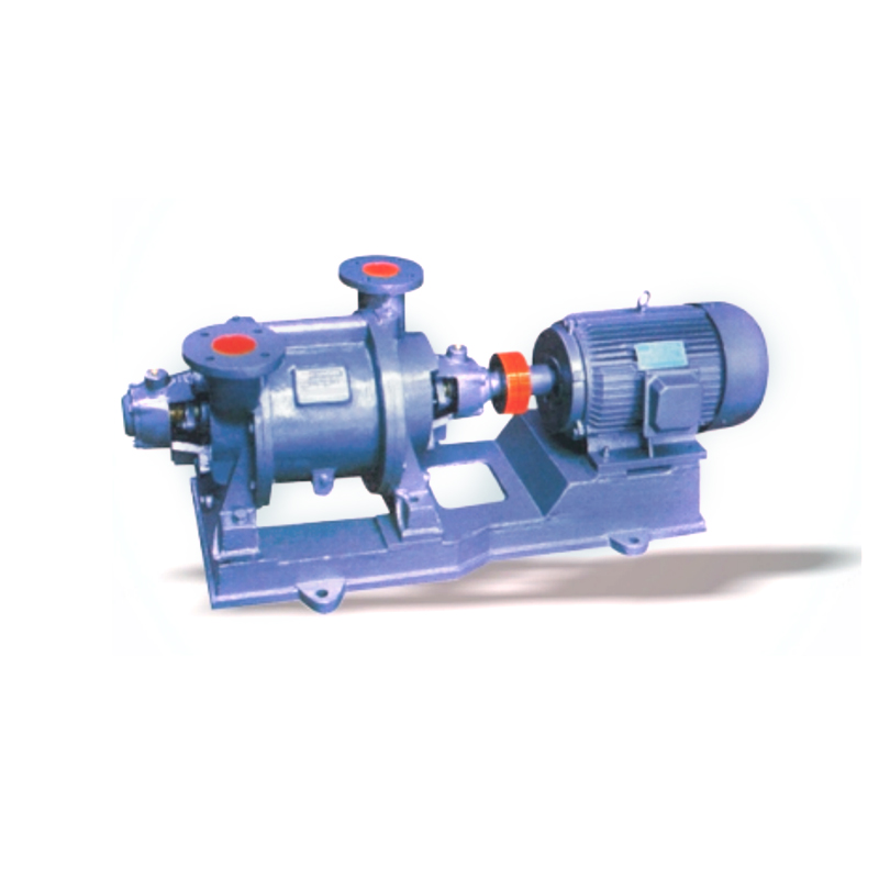 SZ Single Stage Water Ring Vacuum Pump
The SZ Single Stage Water Ring Vacuum Pumps and Compressors are designed to pump or compress air and...
-
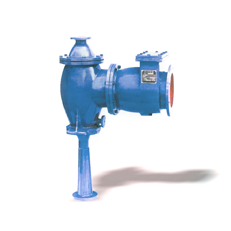 W Type Water Ejector Vacuum Pump
The W Type Water Ejector Vacuum Pump is a mechanical device that combines three effective functions:...
-
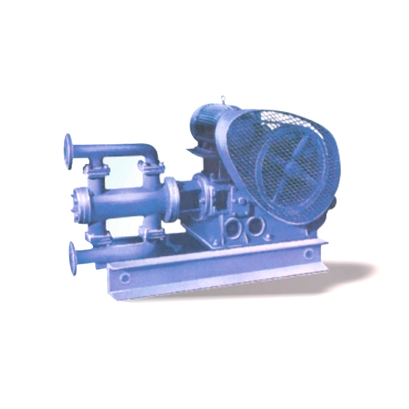 WB Electric Reciprocating Pump
The WB Electric Reciprocating Pump is available in two material options for its flow section: cast i...
-
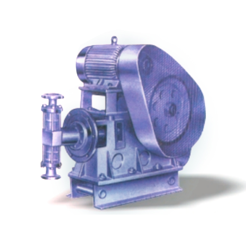 WBR High Temperature Electric Reciprocate Pump
The WBR High Temperature Electric Reciprocate Pump series is specifically designed and manufactured ...
-
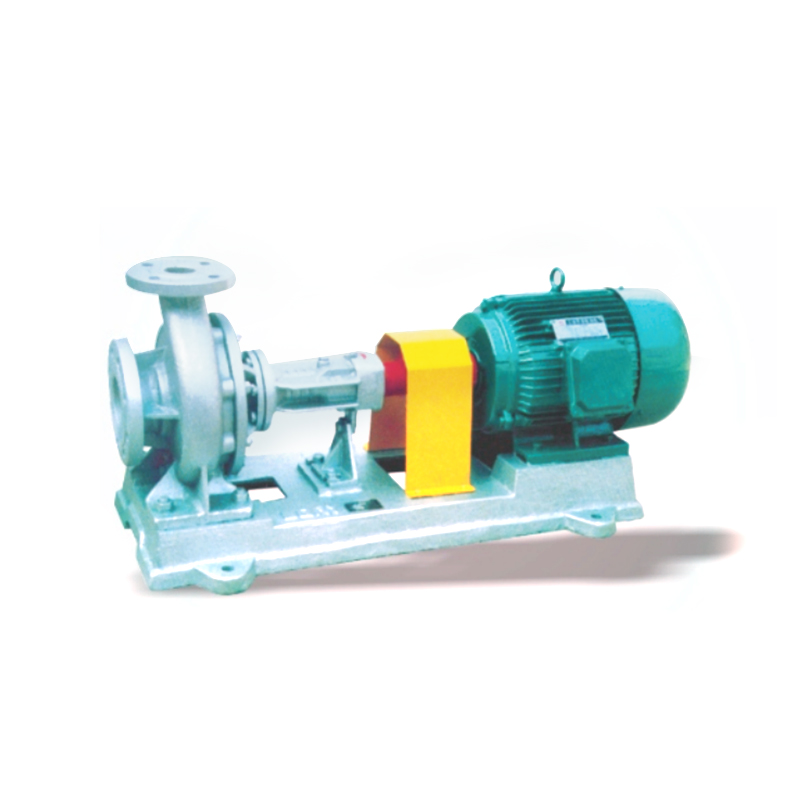 LQRY Heat Conductive Hot Oil Circulation Pump
The LQRY Heat Conductive Hot Oil Circulation Pump is developed by incorporating the advantages of ma...
-
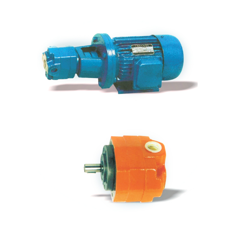 BBG Inner Clutch Cycloid Gear Pump with Motor Drive
The BBG Inner Clutch Cycloid Gear Pump with Motor Drive is a volumetric internal meshing gear pump. ...
-
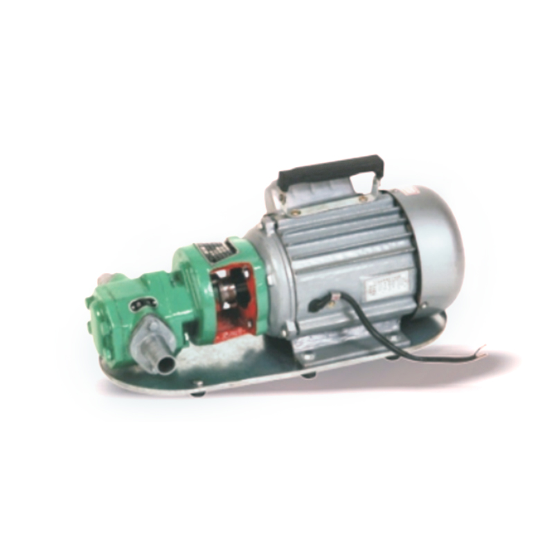 WCB Portable Micro Gear Oil Transfer Pump
The WCB Portable Micro Gear Oil Transfer Pump is designed to transfer clean, neutral oils with a vis...
-
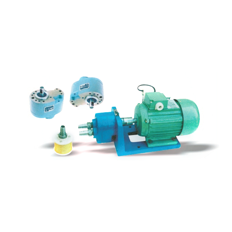 CB-B(S) Low-pressure Gear Oil Pump
The CB-B(S) Low-pressure Gear Oil Pump is a device that converts the mechanical energy output from t...
-
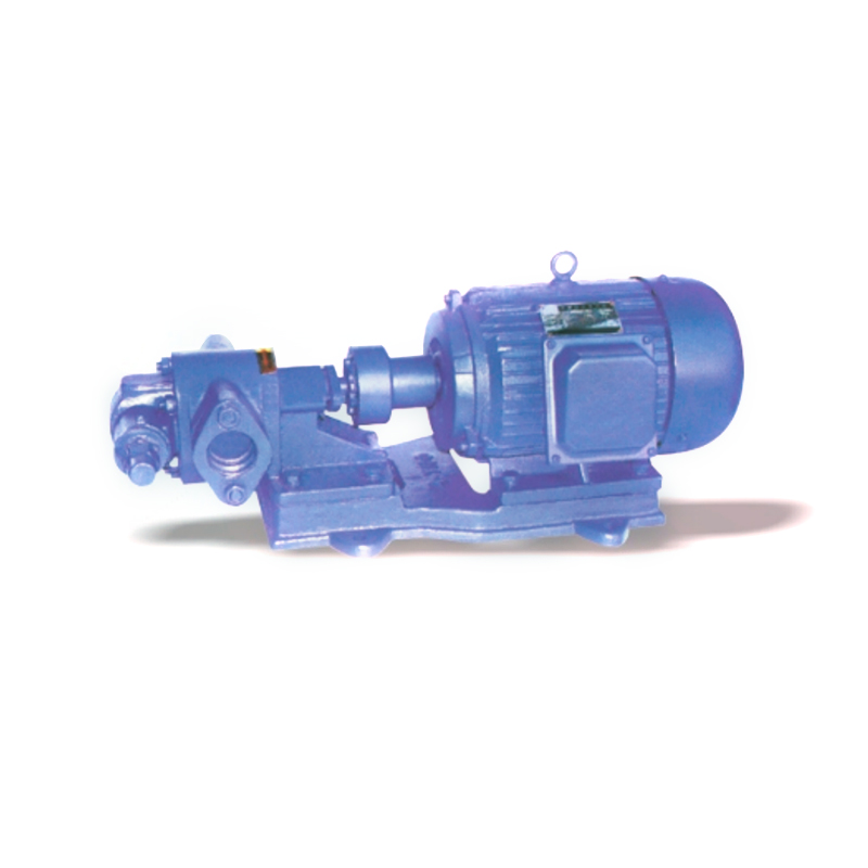 KCB Marine Electric Gear Oil Pump
The KCB Marine Electric Gear Oil Pump is suitable for transporting various lubricating liquids, such...
-
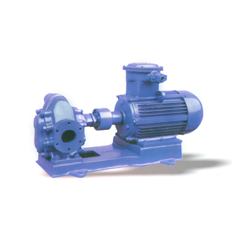 2CY High Pressure Gear Oil Transfer Pump
The 2CY High Pressure Gear Oil Transfer Pump is a traditional product in our country. Its structure ...
-
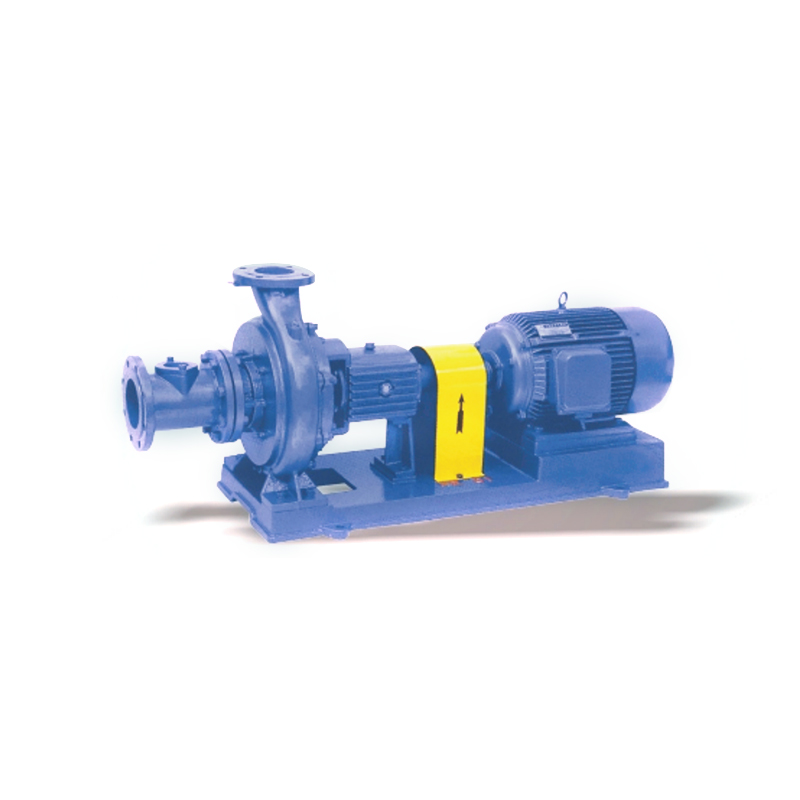 XWJ New Non-clogging Paper Pulp Pump
The XWJ New Non-clogging Paper Pulp Pump is a new, energy-efficient pulp pump. It has been proven th...
-
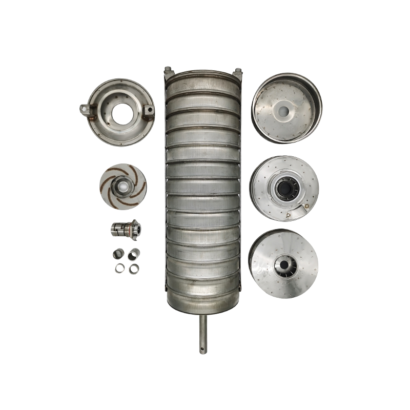 CDL/F Multistage Pump Repair Kit Spare Parts
Our CDL/F Multistage Pump Repair Kit Spare Parts are essential for maintaining the high performance ...
-
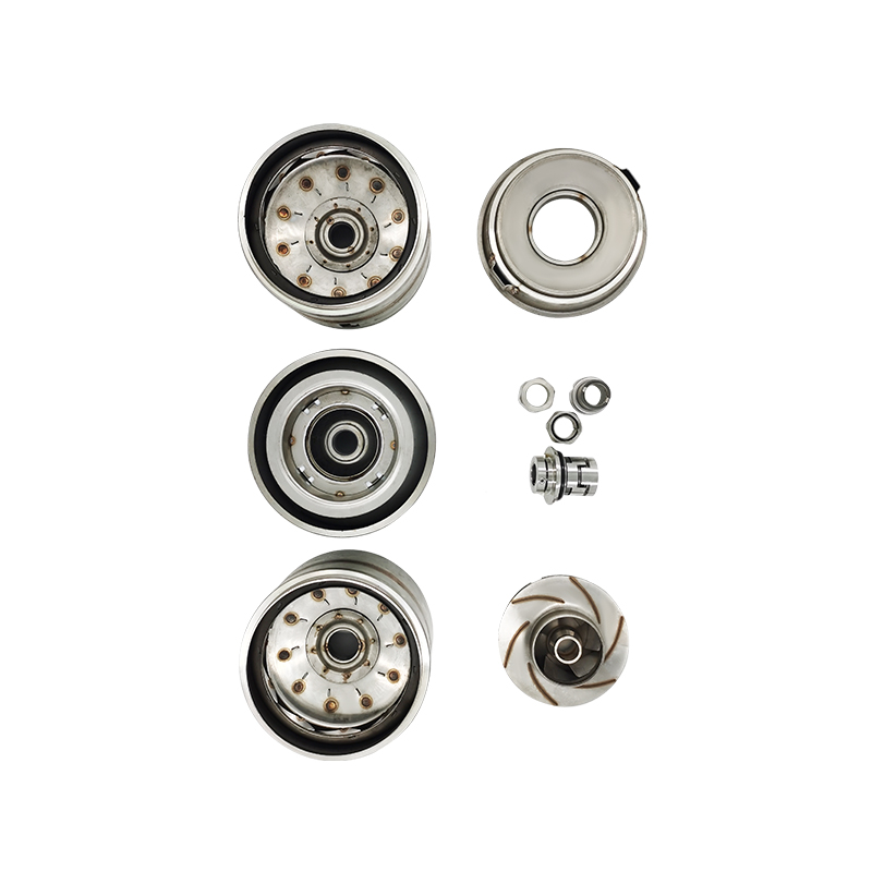 CDL/F Multistage Centrifugal Pump Spare Parts
The spare parts for CDL/F Multistage Centrifugal Pumps include mechanical seals, impellers, and the ...
ChuangKen Advantages
Leading the innovation of fluid technology, we are proud to launch a new generation of water pump solutions. Not only does it have excellent water flow delivery capabilities and achieve precise flow control, but it also achieves a milestone leap in energy efficiency and environmental protection.
-
/ 01 Experience/ 02 Quality
The quality inspection department strictly monitors every production link and the factory inspection rate is 100%.
Application Scenario
Our products are your ideal solution.
-
Garden
Efficient irrigation is achieved by pumping water from water sources to ensure plant growth.
-
Farms
Used for water circulation, oxygenation and feed delivery. The water pump is used to circulate and filter the water in the breeding pond to keep the water clean.
-
Wastewater Treatment Plants
The pump industry plays a key role in wastewater treatment plants, mainly used for the lifting, transportation and circulation of sewage.
-
Fountain
Water is pumped from a reservoir or circulation system and pressurized to create a variety of fountain water effects, such as gushing fountains, atomization or water curtains.
-
Swimming Pool
The pool water is pumped and transported to the filtration system to remove impurities and pollutants to ensure clean water quality.
Zhejiang Chuangken Fluid Co., Ltd.
View About ChuangKen >>
 Play Full Video
Company Profile
View About ChuangKen >>

-
0 m²
Factory Area
-
0 +
Industry Experience
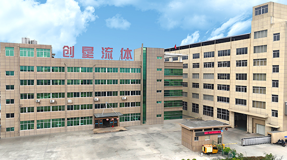
Zhejiang Chuangken Fluid Co., Ltd. is a technology-innovative enterprise that combines research and development with production, specializing in the production of multistage pumps, centrifugal pumps, fire pumps, sewage pumps, complete sets of water supply equipment, control cabinets, etc. It has a long production history, excellent technical personnel, superb production equipment and perfect testing methods.
Recent News
Learn about our industry exhibition information and recent events in our company.
-
Why Diesel Engine Pumps Matter in Industrial Operations Moving water and other compatible fluids is a routine requirement across construction sites, agricultural operations, industrial facilities, and emergency drainage projects. In locations where a stable electrical supply is unavailable or difficult to access, diesel engine pumps can provide a practical alternative. Their built-in diesel power source allows the pump unit to operate independently of a fixed electrical connection. A Diesel Engine Pump Factory brings together engine selection, pump assembly, component matching, and performance testing. These activities help manufacturers develop equipment for different flow requirements, operating conditions, and installation arrangements. For equipment distributors and project contractors, understanding how these products are designed and manufactured can make product selection more straightforward. Pump capacity, engine output, fluid characteristics, and operating conditions all influence which configuration is suitable for a particular application. How Factory Production Shapes Pump Performance A diesel engine pump is made up of several connected systems. The diesel engine supplies mechanical power, while the pump converts that power into fluid movement. A coupling or drive arrangement transfers energy between these components, and the supporting frame keeps the assembly positioned during operation. At a Diesel Engine Pump Factory, production generally involves several stages, including component preparation, engine and pump matching, mechanical assembly, and functional checks. The exact workflow depends on the product design and the manufacturer's production arrangements. Matching the engine to the pump is an important part of the process. A pump intended for high flow at relatively low discharge pressure may require a different configuration from one designed to move water through a long pipeline or deliver it to an elevated location. The inlet and outlet dimensions, impeller design, shaft arrangement, and connection type also affect how the finished unit integrates with the wider system. Consistent assembly procedures help manufacturers keep these components aligned with the intended product specifications. Custom Configurations for Different Pumping Needs Not every pumping project requires the same equipment arrangement. Some customers need a compact unit that can be moved between work areas, while others require a stationary assembly designed around a particular pipeline or installation space. A Diesel Engine Pump Factory may offer different frame structures, engine ratings, pump types, and connection arrangements. The available choices depend on the manufacturer's engineering capabilities and existing product range. OEM and ODM services can also be relevant for distributors developing their own equipment brands. Depending on the supplier's capabilities, cooperation may involve product appearance, nameplates, packaging, selected structural details, or specifications for a particular market segment. Before confirming a customized order, both parties should establish the required operating parameters and the scope of the changes. This helps ensure that the proposed configuration matches the intended application rather than relying on general product descriptions. Production Consistency and Product Selection A diesel engine pump must function as an integrated assembly rather than a collection of unrelated components. Engine output, pump characteristics, mechanical connections, and structural support all contribute to how the unit performs under its intended operating conditions. For distributors and industrial equipment suppliers, a capable manufacturing partner should provide understandable specifications, clear model distinctions, and information that supports application matching. These details are particularly useful when several pump configurations share a similar appearance. A Diesel Engine Pump Factory serves an important role in connecting manufacturing processes with practical pumping requirements. By considering application conditions, component compatibility, production procedures, and available configurations, businesses can identify equipment that fits their operational needs and build a more clearly organized product portfolio.
23 -
How the System Actually Works At its core, the technology is straightforward. A pump moves water from a tank or municipal line into a building's distribution network. Attached to that pump is a variable frequency drive, a device that adjusts the motor's speed in real time. Pressure sensors placed along the pipe network send constant readings back to a controller. If demand rises—say, at breakfast time when dozens of taps open at once—the controller tells the motor to speed up. If demand falls, the motor slows down. The result is pressure that stays within a narrow, predictable range no matter how many fixtures are running. Traditional systems work differently. Fixed-speed pumps either run at full power or shut off entirely. To handle peak demand, they are sized for the busiest moment of the day, which means they run oversized during the remaining hours. Pressure relief valves dump excess force, and pumps cycle on and off repeatedly, wearing out motors and seals. A Variable Frequency Constant Pressure Water Supply Unit smooths out those spikes, letting the equipment match its output to the actual workload. Where People Are Installing It The applications stretch across many settings. Hotels rely on the units to keep guest showers consistent even when banquet halls and kitchens run simultaneously. Hospitals use them to protect sensitive equipment that depends on stable flow. In manufacturing plants, constant pressure supports cooling loops and cleaning stations. Residential developers have also taken notice, particularly in taller buildings where gravity alone cannot deliver water to upper floors at usable pressure. Recent industry conversations suggest growing interest from commercial property managers facing rising energy bills. Because a variable frequency drive only draws the power it needs, motors spend much of their time running below full speed. Engineers familiar with the technology note that moderate pump speed reductions can translate into noticeable drops in electricity consumption, since power demand falls sharply as speed decreases. Questions Buyers Are Asking Q: How does the controller respond to a burst pipe or sudden leak? A: Pressure sensors detect the abnormal drop within seconds, and the controller either slows the pump or triggers a shutdown sequence, depending on how the system is configured. Engineers typically pair this response with buffer tanks to absorb sudden changes in demand. Q: What happens during a power interruption—does pressure collapse instantly? A: Not necessarily. Installations with buffer tanks or elevated reservoirs retain a reserve that keeps water flowing for a period after the power cuts out. Projects with stricter continuity requirements usually add backup power arrangements, though the details vary by installation. Q: Why are water utilities following this trend? A: Stable building-level pressure reduces strain on municipal lines during peak hours, and lower energy draw at the pump level eases demand on local grids. None of this happens overnight, but each installation adds a small measure of resilience to the wider network. A Steady Trend, Not a Fad The appeal of the Variable Frequency Constant Pressure Water Supply Unit ultimately comes down to a simple idea: match the machine's effort to the task at hand. In a world of rising utility costs and aging building stock, that idea keeps finding new audiences. Whether in a hospital wing, a hotel tower, or a suburban apartment block, the technology earns its keep quietly—one steady, unremarkable shower at a time.
16 -
Different Projects Call for Different Pump Designs Wastewater handling involves a wide range of operating conditions. Residential buildings, commercial facilities, industrial sites, and municipal drainage systems may all need equipment to move sewage or wastewater from one location to another. A sewage pump factory must understand these differences when developing and supplying products for different projects. Sewage pumps are designed to handle wastewater that may contain suspended solids and other materials. Depending on the application, available products may include submersible sewage pumps, non-clog pumps, and wastewater lifting pumps. Each design serves particular installation and operating requirements. For distributors, contractors, and equipment suppliers, choosing a pump begins with understanding the liquid, flow requirement, discharge conditions, and installation environment. These details help connect a product's design with the work it needs to perform. Pump Structure Depends on the Intended Application A sewage pump is more than a motor connected to an impeller. Its housing, inlet, discharge outlet, shaft arrangement, and impeller design all influence how the equipment handles wastewater. Submersible sewage pumps operate while immersed in the liquid being pumped. Their compact arrangement can suit sewage pits, collection tanks, and drainage installations where the pump sits below the liquid level. Other sewage pump designs may be installed outside the liquid, depending on the system layout. The choice depends on available space, pipe connections, access requirements, and the operating conditions specified for the project. A sewage pump factory may offer several structural configurations to serve different installation needs. Buyers should compare the actual product drawings and specifications rather than assuming that pumps with similar capacities share the same construction. Impeller Design Influences Solids Handling Wastewater can contain suspended particles, fibrous materials, and other solids. For this reason, impeller design is an important consideration when selecting a sewage pump. Common designs include vortex impellers, channel impellers, and other configurations intended for particular wastewater conditions. A vortex design creates a flow pattern that can reduce direct contact between solids and the impeller, while channel designs use passages to move liquid through the pump. The suitability of each design depends on the type and size of solids, the required flow, and the pump's specified operating range. No single impeller arrangement fits every sewage application. When discussing a project with a supplier, buyers should describe the wastewater characteristics and the expected operating conditions. This gives the manufacturer a clearer basis for identifying suitable pump models. Materials and Motor Options Shape Product Selection Pump materials vary according to the product design and intended working conditions. Cast iron is commonly used in sewage pump housings, while stainless steel and other materials may be specified for particular components or applications. Material selection should reflect the liquid being handled, the installation conditions, and the product specification. Buyers may need to compare housing materials, shaft materials, sealing arrangements, and impeller construction when evaluating different models. Motor power is another important consideration. The required motor depends on factors such as flow rate, total head, pipe resistance, and operating conditions. Selecting a pump by motor power alone may not provide enough information to determine whether it suits a particular system. Sewage Pumps Serve Multiple Market Segments Sewage pumps are used in residential drainage, commercial buildings, wastewater collection stations, industrial facilities, and municipal pumping systems. Although these applications share the need to move wastewater, their operating conditions can differ considerably. A residential installation may involve a relatively compact sump or lifting station. Commercial buildings may require pumps for basements, underground facilities, or wastewater collection points. Industrial applications can involve wastewater with different solids content and liquid characteristics. These differences influence pump selection, installation arrangements, and the information required during procurement. A sewage pump factory serving multiple markets needs a product range that addresses varied operating conditions rather than treating every project as identical.
09 -
An Intelligent Constant Pressure Water Supply System keeps water pressure steady across changing demand by linking pumps, sensors, and electronic controls. The setup responds to real-time flow changes so that outlets continue to receive consistent pressure without manual adjustment. This approach appears in multi-story buildings, industrial plants, and municipal networks where pressure stability supports reliable operation. Core Components and Layout The main elements include one or more centrifugal pumps, a pressure sensor, a frequency converter, and a programmable controller. Pipes and valves complete the hydraulic circuit. The Intelligent Constant Pressure Water Supply System places the sensor at a representative point in the discharge line so that it measures the actual pressure delivered to users. The controller receives the sensor signal and compares it with a set value. When pressure drops, the controller raises pump speed through the frequency converter. When pressure rises above the target, speed decreases. This closed-loop arrangement forms the technical heart of the unit. Working Principle of Pressure Regulation Water demand fluctuates during the day as outlets open and close. A conventional fixed-speed pump would cause pressure to swing widely under these conditions. The Intelligent Constant Pressure Water Supply System avoids that swing by continuous speed adjustment. The frequency converter changes the electrical frequency supplied to the pump motor, which directly alters rotational speed and therefore output flow. Because the relationship between speed and pressure is predictable, the controller can calculate the exact speed needed to restore the set pressure within a short interval. The result is a smooth pressure curve rather than sharp peaks and valleys. Pump and Drive Integration Pumps are selected for the required head and flow range of the installation. Vertical multistage or horizontal end-suction designs both appear, depending on space and duty. The motor is matched to the frequency converter so that it can operate efficiently across a broad speed band. Soft-start and soft-stop functions built into the converter reduce mechanical stress on the impeller and shaft during acceleration and deceleration. The Intelligent Constant Pressure Water Supply System therefore maintains pressure while limiting the mechanical load on rotating parts. Applications in Practical Settings Multi-story commercial buildings use the system to serve upper floors without oversized tanks. Manufacturing plants rely on steady pressure for process lines that require consistent water delivery. Municipal booster stations install similar configurations to maintain pressure across extended distribution zones. In each case the Intelligent Constant Pressure Water Supply System replaces earlier methods that depended on large storage tanks or constant-speed pumps with bypass valves. The electronic control approach reduces the physical footprint and allows tighter pressure bands. Assembly and Technical Considerations During assembly the sensor is calibrated against a known pressure source, and the controller parameters are entered according to the system curve of the selected pumps. Pipework is arranged to minimize turbulence near the sensor location so that readings remain accurate. The complete Intelligent Constant Pressure Water Supply System is tested under simulated demand changes before installation. Flow is varied while the controller holds the set pressure, confirming that the frequency converter and pumps respond correctly. These steps ensure the unit performs as designed once placed in service. The combination of sensor feedback, variable-speed drives, and coordinated control produces a water supply arrangement that holds pressure within a narrow band under ordinary operating conditions. The Intelligent Constant Pressure Water Supply System therefore provides a practical technical solution for sites that require steady delivery without continuous manual intervention.
02 -
Many centrifugal pumps need their casing filled with liquid before they can start moving fluid — no exceptions, no workarounds. A self-priming pump solves that particular headache by clearing air out of the suction line on its own, without an operator manually filling the line first. For industries dealing with fluctuating liquid levels, that difference changes how equipment gets specified from the start. The Core Mechanism Behind Self-Priming A self-priming pump keeps a reservoir of liquid inside its casing even after shutdown. When the pump restarts, this retained liquid mixes with the air pulled in from the suction line, creating a liquid-air mixture the impeller can move. That mixture gets separated inside the casing — air escapes through the discharge, liquid recirculates back to continue the priming cycle — until the air pocket clears and normal pumping resumes. This cycle typically takes anywhere from under a minute to several minutes, depending on suction lift height, pipe diameter, and how much air needs clearing. Engineers specifying a self-priming pump for a particular application usually look closely at this priming time, since it affects how quickly a system responds after a dry start or after liquid levels drop below the suction inlet. Where the Design Shows Its Value Applications with variable liquid levels are where a self-priming pump earns its keep. Construction dewatering, wastewater transfer, and tank drainage all involve suction conditions that shift constantly — sometimes the suction line sits fully submerged, sometimes it doesn't. A standard centrifugal pump would need manual priming every time air entered the line, which isn't practical on a job site where conditions change hour to hour. Chemical processing and industrial transfer operations also lean on this pump type when handling liquids that can't be left standing in exposed suction lines, or when the pump sits above the liquid source rather than below it. In configurations where a flooded suction isn't feasible, a self-priming pump becomes less of a convenience and more of a practical requirement. Internal Components That Enable Priming Inside a self-priming pump, the casing geometry is shaped specifically to trap the liquid reservoir needed for re-priming. Many designs include a separation chamber above or beside the impeller, where air bubbles rise and escape while liquid drops back down to rejoin the recirculation path. Impeller design also plays a role — some models use a recessed or semi-open impeller to handle the air-liquid mixture without excessive wear during the priming phase. Material selection varies by application. Cast iron and stainless steel casings appear often in industrial settings, while lighter aluminum or engineered polymer bodies show up in portable units used for construction or emergency dewatering, where weight and mobility matter as much as pumping capacity. Matching Pump Type to the Job Not every application calls for a self-priming pump. If the suction line stays flooded at all times and air entry isn't a concern, a standard centrifugal pump often does the job with less complexity and fewer internal components to wear over time. The self-priming design earns its added cost and complexity specifically in situations where suction conditions are unpredictable, intermittent, or above the fluid source. Flow rate, total head, and the viscosity of the liquid being handled all factor into selecting the right self-priming pump for a given system. Pumps designed for clear water behave differently than those built to handle solids-laden wastewater or slurry, and matching the internal clearances and materials to the actual fluid prevents a mismatch between pump capability and job requirements.
25 -
A Simple Structure With a Clear Flow Path Industrial pumping does not always require a complicated hydraulic arrangement. In many water and process systems, a straightforward centrifugal structure can provide a practical way to move liquid from one point to another. This is where the Single-stage Single-suction Centrifugal Pump has an important place in industrial equipment. Its name already explains two key structural features. “Single-stage” means the pump uses one impeller stage to generate hydraulic energy. “Single-suction” means liquid enters the impeller from one side. These characteristics create a relatively direct internal flow path, making the pump easier to classify according to its hydraulic structure. For equipment distributors and engineering suppliers, understanding this structure helps when matching pump models to different system requirements. What Happens Inside the Pump? The working process starts at the suction inlet. Liquid enters the pump casing and reaches the impeller eye. Once the impeller rotates, centrifugal force moves the liquid outward toward the impeller perimeter. The casing then guides the moving liquid toward the discharge outlet. During this process, part of the mechanical energy supplied by the motor is converted into pressure energy. The Single-stage Single-suction Centrifugal Pump therefore relies on a relatively compact sequence: suction, impeller rotation, radial movement, casing flow, and discharge. Each section has a specific role, and the relationship between these components determines the hydraulic behavior of the complete unit. Impeller Design Shapes Hydraulic Behavior The impeller is at the center of the pumping process. Its diameter, blade geometry, passage shape, and rotational speed influence how liquid moves inside the pump. Different impeller configurations can be developed for different flow and head requirements. A pump designed for relatively large flow may use a hydraulic geometry different from one intended for greater pressure generation. This is one reason the Single-stage Single-suction Centrifugal Pump should not be identified only by its external appearance. Two pumps can share a similar casing shape yet have different hydraulic characteristics because of their impeller dimensions and internal passages. For manufacturers, controlling these relationships is an important part of pump design and production. Casing Turns Motion Into Useful Pressure The casing is more than an enclosure around the rotating assembly. Its internal passage helps collect liquid leaving the impeller and direct it toward the discharge side. Depending on the pump structure, the casing may use a volute-shaped passage that gradually manages liquid velocity as flow moves toward the outlet. The geometry of this passage has a direct relationship with hydraulic performance. In a Single-stage Single-suction Centrifugal Pump, casing and impeller design need to work as a matched hydraulic pair. Changing one component can influence the flow pattern inside the other, which is why dimensional coordination matters during manufacturing. Shaft Alignment Connects the Mechanical Assembly The pump shaft transfers rotational power from the drive unit to the impeller. Its position needs to remain properly related to the casing, impeller, bearing arrangement, and sealing section. For industrial equipment suppliers, shaft configuration is an important product detail because it affects how the pump connects to the wider drive system. The mechanical arrangement also influences how manufacturers organize machining and assembly processes. Shaft dimensions, impeller mounting, bearing positions, and coupling arrangements all need to correspond to the selected pump configuration. This gives the Single-stage Single-suction Centrifugal Pump a useful combination of hydraulic and mechanical characteristics within one equipment package. Flow Rate and Head Guide Model Selection Pump selection begins with the liquid movement required by the system. Flow rate describes how much liquid needs to pass through the pump during a given period, while head represents the energy required to move that liquid through the system. These two parameters provide a starting point for choosing a suitable pump model. Pipe diameter, system resistance, liquid characteristics, inlet conditions, and operating speed can also influence the final selection. For distributors and project suppliers, presenting these details clearly makes the Single-stage Single-suction Centrifugal Pump easier to match with industrial applications.
18
Copyright © Zhejiang Chuangken Fluid Co., Ltd. All Rights Reserved.
Intelligent Constant Pressure Water Supply System Factory
 浙公网安备33032402001888号
